® 520M/520TS Manual and Thermostatic Power Shower Units Installation instructions & User guide IMPORTANT: This booklet should be given to the customer after installation and demonstration. WARNING: Under no circumstances should this unit be connected to the mains water supply.
Thank you for choosing a quality 'Redring' product manufactured in Peterborough, England. HOW TO USE YOUR 'REDRING' POWER SHOWER CONTENTS 1. Ensure the electricity and water supplies are turned on to the unit. 2. Your shower has 2 control knobs (see diagram 1). Knob 'A' controls the Start/Stop operation and the water flow rate of the Shower unit. Knob 'B' controls the temperature of water and also incorporates a temperature limiter. 3. To start the shower turn knob 'A' clockwise from the STOP position.
Top Fixing Holes Diagram 2 Motor Terminal Block Rating Plate Position Cable Clamp PCB Enclosure Commissioning Link Pump Assy Cold Inlet Port Hot Inlet Port Solenoid Bottom Fixing Holes Side Section Filter Housing Outlet Mixer Chamber The limiter is factory set but can be adjusted to suit on site conditions. If the position of the limiter requires adjustment please refer to the section in the commissioning procedure (page 9). 8.
Diagram 4 The spray head rotates through approximately 140o c) Water too cold Turn Temperature Control Knob (B) anti-clockwise to a higher number on the temperature scale (see diagram 1). Check that hot water is available in the hot water cylinder. The ideal thermostat setting for the hot water storage cylinder is 60oC (140oF). Check that the HOT water isolating valve is open. If possible, reposition temperature limiting device so that more movement of Knob 'B' is allowed.
b) Pump operates when motor is switched off Check for faulty potentiometer switch, (located under knob 'A' inside front cover). Switch should be open circuit when turned fully anti-clockwise. c) Water too hot Blockage in filter causing obstruction in water supply. Check and clean (see page 10). d) Water too cold Blockage in filter causing obstruction in water supply. Check and clean (see page 10).
3. a) b) c) 3. 4. 5. 6. 6 unit ie. Mounted as shown in diagrams 5/6. Choose a flat piece of wall to avoid possibility of distorting the backplate thus making the front cover a poor fit. Adjust the positions to get the most convenient arrangement taking the following into account : The possible need to use the handset over the sink for hair washing etc. The shower unit must not be mounted in the direct spray from the handset.
Diagram 9 Diagram 8 Short fixing screw A Long fixing screw Simply push in tube to attach Side section 'O' ring seals Combined inlet elbow B 1. Surrey Flange (Top entry cylinder flange) Fitting Instructions. The hot connection to the Shower unit can be taken directly from the hot cylinder using a Surrey Flange. Diagram 10 shows how this flange should be fitted. 2. Essex Flange (Side entry cylinder flange) Fitting Instructions.
9. With an isolating valve connected, flush the pipework through to remove particles etc. before making the final connection to the shower. A blockage in the waterways (particularly the spray rings and filter) will prevent the shower unit working properly. 10. The shower unit should only be used with "Redring" recommended fittings.
C) Electrical 1. The electrical installation must be in accordance with current BS. 7671 (I.E.E. regulations). 2. The unit should be connected into a switched 3 amp double pole fused spur, with a minimum contact gap of 3mm in each pole. The switch must be fitted outside the bathroom. Alternatively, a double pole ceiling switch, with a pull cord and a minimum contact gap of 3mm in each pole could be used inside the bathroom.
Gently prise away the limiter from the front cover and rotate to new position. Rotate clockwise for a cooler stop position and anticlockwise for a warmer stop position. Ensure that the limiter is pressed firmly home. Reassemble Temperature Control Knob 'B' over the drive on the mixer unit and fix into place with a screw. Check that it's movement is restricted sufficiently. Also check operation of temperature override button (see diagram 1).
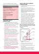
ASSEMBLY OF RISER RAIL, HANDSET AND SOAP DISH Diagram 12 Additional knock out fixing slot if required Removable insert in soap dish for ease of cleaning Locating Key 11
Guarantee We, Applied Energy Products Ltd., guarantee that should this power shower prove to be defective by reason of faulty workmanship or material within 24 months (outside of U.K. please contact your local distributor) of the date of purchase or commencement of hire purchase we will replace the defective parts FREE OF CHARGE on condition that: • The appliance has been correctly installed and used only on the supply circuit or voltage stamped on the rating plate.