REDRING ACTIVE ELECTRIC SHOWER Installation and User Guide IMPORTANT: This booklet should be left with the user after installation and demonstration
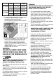
THIS APPLIANCE CAN BE USED BY CHILDREN AGED FROM 8 YEARS AND ABOVE AND PERSONS WITH REDUCED PHYSICAL, SENSORY OR MENTAL CAPABILITIES, OR LACK OF EXPERIENCE AND KNOWLEDGE IF THEY HAVE BEEN GIVEN SUPERVISION OR INSTRUCTION CONCERNING USE OF THE APPLIANCE IN A SAFE WAY AND UNDERSTAND THE HAZARDS INVOLVED. CHILDREN SHALL NOT PLAY WITH THE APPLIANCE. CLEANING AND USER MAINTENANCE SHALL NOT BE MADE BY CHILDREN THIS SHOWER IS DESIGNED AND APPROVED TO EN-60335 WITH THE HANDSET PROVIDED.
These can result from toilets being flushed or taps being turned on and off. When this happens your showering temperature will be held within a controlled band, provided that the minimum pressure required by the shower is maintained (page.4) If the water pressure falls below the minimum pressure required, it is likely that the pressure switch will turn off the power to the heating elements, resulting in a cold shower. DO NOT place items such as soap, shampoo or other such bottles on top of the unit.
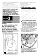
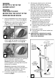
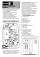
3 5 10. Your shower is provided with 2 wall-fixing positions in the backplate and 2 alternatives (compatible with S range showers). The top-fixing hole is a ‘key-hole’ slot, and should be marked and drilled first. Tighten top screw with head protruding about 10mm from the wall and hook the backplate over the screw head. This allows for correct and accurate alignment of your shower before marking and fixing the bottom position.
Rating 7.2 / 6.6kW 240 / 230V 8.5 / 7.8kW 240 / 230V Cable Sizes 4.0mm² 6.0mm² 32A Type B MCB Cable Length 21m Max. 35m Max. 6.0mm² 10.0mm² 40A Type B MCB 27m Max. 45m Max. 6.0mm² 10.0mm² 40A Type B MCB 27m Max. 45m Max. 6.0mm² 10.0mm² 45A BS.1361 fuse 12m Max.* 21m Max.* Fuse / MCB WARNING: BEFORE CONNECTING THE PIPE WORK TO THE SHOWER, ENSURE THAT THE PIPE WORK IS FULLY FLUSHED OUT. 1.
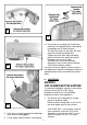
WARNING: DO NOT FIT A TAP ON THE SHOWER OUTLET. WARNING: TAKE CARE TO AVOID RESTRICTING THE OUTLET OF THE PRESSURE RELIEF DEVICE. 9. Set the power select knob to cold (single blue bar) 9 o’clock position and turn temperature knob fully anti clockwise to allow the unit to fill with water prior to any heat settings being selected. 10.
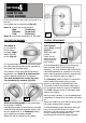
Ensure the electricity and water are turned on to the unit. Your shower has 2 control knobs (fig.12). Knob ‘A’ controls the ‘High’ ‘Economy’ ‘Cold’ Knob ‘B’ controls the power selection. - (3 red bars) - (2 red bars) - (1 blue bar) temperature of the water. 12 TO START THE SHOWER TO STOP THE SHOWER Turn Knob ‘A’ to your desired Power setting (normally ‘High’). Water will start to flow (fig.10). Turn ‘Knob A’ to the ‘Stop’ position (fig.13). Water will cease to flow.
WARNING: DO NOT SWITCH THE SHOWER ON IF YOU SUSPECT IT OF BEING FROZEN. WAIT UNTIL YOU ARE SURE IT HAS THAWED OUT. WARNING: DO NOT OPERATE THE SHOWER IF WATER IS DISCHARGED FROM THE PRESSURE RELIEF VALVE. MAINTENANCE IS REQUIRED BEFORE IT CAN BE USED AGAIN. WARNING: CONSIDERATION SHOULD BE GIVEN TO SUPERVISING THE YOUNG, ELDERLY AND THE INFIRM WHILST THEY USE THIS SHOWER.
Spray pattern poor Broken parts Clean the shower handset. Please contact us on our after sales service department (See Section 5). Fitting instructions are provided with most spares SELF HELP PROFESSIONAL SERVICE If the shower is not working satisfactorily, make the following checks before calling out the installer. Any one of these adjustments could restore the performance. If the previous ‘Self Help’ checks fail to restore performance, you should seek professional help.
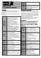
6. As a further safeguard, a thermal cut-out switches the power off if the water temperature climbs above the set limit. This cut-out, which gives an audible click, may also operate due to residual heat when the shower is switched off. It will reset itself if water is run through the shower for 10 to 20 seconds. 1. Water is heated instantaneously as it flows over the heating elements in the heat exchanger (fig.14). 7.
Effect of Seasonal Incoming Water Temperature Changes The required water temperature is achieved by adjusting the rate of water flow. The diagram shows the principle involved in relating temperature rise to flow rate. The higher the water rate the lower the temperature and vice versa. The temperature of the water supplied from the mains can vary considerably throughout the year from 5 to 20°C. This means that in the winter, flow rate will be less than in the summer to achieve the same outlet temperature.
GUARANTEE Terms and Conditions for UK (outside UK contact your local distributor) We guarantee this product for domestic use only, for a period of 24 months from the date of purchase.