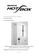
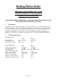
Redring Hotbox Boiler Models L318 and LP330 User and Installer Instructions Please keep these instructions safe, should you move house, please hand them over to the next occupier.
Redring Hotbox Boiler THE HALOGEN BOILER, L318, LP330 HALOGEN POWERED WALLMOUNTED BOILER USER&INSTALLERS INSTRUCTIONS PLEASE KEEP THESE INSTRUCTIONS SAFE. SHOULD YOU MOVE HOUSE, PLEASE HAND THEM OVER TO THE NEXT OCCUPIER. 1. Introduction The Halogen Boiler is a wall-mounted appliance, suitable for installation onto small sealed heating systems.
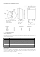
Overall Dimensions & Minimum Clearances Clearances Side Top Bottom Front 3.
If the boiler is to be placed in a cupboard this cupboard should not be used as a storage cupboard. Ventilation should be provided as detailed below. Ventilation This boiler does not require a purpose provided air ventilation in the room, however it does require room air to circulate through the boiler to ensure the convection heat output performance is maintained.
Example: 30L system total capacity requires an expansion vessel capacity of 30 x 0.0833 = 2.5 litres with a 0.5 bar vessel charge and system cold fill pressure. Filling Point The heating system must be provided with a suitable filling mechanism to both complete the initia l fill and top up the system if necessary. The filling device must comply with Water Supply (water fittings) Regulations and the local Water Authority Regulations. Refer to BS 5376: for guidance.
Location Before installing the boiler check that the chosen location is suitable, ensuring a dequate clearance is available for both installation and servicing. The appliance must be mounted on a flat vertical wall. Prepare the Appliance Remove the front panel by unscrewing the two screws at the bottom of the case. Rotating the case forwards at the bottom 10 mm and lifting it off in an upward direction.
Allow the heating system to reach operating temperature and then examine for water leaks. Turn off the boiler and drain whilst still hot. Refill and vent the heating system ensuring all air is cleared from the system and the cold fill pressure is set at the design pressure. The pressure gauge should be at 0.5 bar. Set the indicator on the pressure gauge to co-inside with this initial cold fill pressure.
Replacing a bulb • • • Remove the lid from the bulb box, remove the faulty bulb and replace with a new bulb. Do not touch the bulb with bare fingers, as this will reduce the life of the bulb. Use clean tissue paper or similar to hold the bulb. Check that the bulb is seated correctly on the contacts. Replace the top of the bulb box, locating it onto the pins provided.
Replacing the expansion vessel • • • • Isolate the boiler using the appliance isolation valves on the flow and return connections to the boiler. Remove the expansion vessel from the pipe work. Refit a replacement expansion vessel in reverse order using a recognised method of sealing the threaded joint. Open the isolation valves, ensure the system cold fill pressure is correct, there are no water leaks and the system is correctly vented of all air.
Fault Finding Chart If the radiators do not get hot or do not reach the boiler flow operating temperature follow the guide below to establish the possible cause.
9.
10. Item 1 2 3 4 5 6 7 8 9 10 11 12 13 14 15 16 Part Number 97392070. 97392071. 97392072. 97392073. 97392074. 97392075. 97392076. 97392077. 97392078. 97392079. 97392080. 97392081. 97392082. 97392083. 97392084. 97392085.
GUARANTEE Terms and Conditions for UK & ROI (outside UK & ROI contact your local distributor) We, Applied Energy Products Limited, guarantee this product for domestic use only, for the period of 12 months from the date of purchase.