
User manual


23
b) Inserting the Flight Battery into the Quadrocopter
To ensure a sufciently good satellite reception, the quadrocopter should be set up on a free eld, where no high-
voltage lines, power masts, metal constructions or other obstacles may impair GPS reception.
Stay away from broadcasting systems and other facilities that may negatively inuence the electromagnetic conditions
in your environment.
The ight eld should also be free of obstacles such as buildings or trees to ensure unimpaired ight operation.
Choose a day with good whether and the least possible wind.
Before inserting the ight battery in the quadrocopter, check the voltage situation. For this, briey push the on/off
button (1) at the ight battery. All four LEDs must be lit for two seconds.
Switch on the remote control transmitter and check the correct function of the transmitter with the display. The trim-
ming displays (see gure 10, items 5, 6, 8 and 10) must be in the middle position. If this is not the case, the trimming
must be set (see the following chapter 11. g).
Turn the rotating encoder „VRB“ to the centre position or check the centre position of the controller.
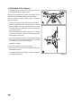
Now push the deactivated ight battery (see gure 16, item 1) into the quadrocopter with the charge connection con-
tacts rst. Slightly push the grooved surface of the battery lock (see gure 16, item 2) so that the locking tab can latch
and the ight battery is safely held in the quadrocopter.
When the ight battery has been inserted into the quadrocopter and is locked properly, switch on the ight battery with
the on/off button (see gure 6, item 1), so that the quadrocopter is supplied with power
Figure 16
The status LEDs (see gure 16, item 3) light up yellow (red and green) and the quadrocopter performs a self-test. After
a brief time, the downward-pointing LEDs in the book arms will ash and the quadrocopter will emit a brief signal.
The gimbal swivels the camera holder into the home position and the status LEDs will briey go out and then start to
ash. The meaning of the ashing impulses is described in more detail below.
When the binding between the transmitter and receiver is correct, the display of the remote control shows the voltage
supply of the receiver (see gure 10, item 4). Push the buttons „UP“ or „DOWN“ at the transmitter to get more infor-
mation about the current reception of the GPS satellite.