
User manual


21
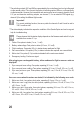
Attention!
The status messages correspond to firmware 2.1 and may deviate in a subsequent
version. Therefore, always observe the text file in the firmware used by you.
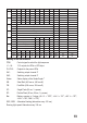
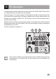
Verify the signals SA1, SA2 and status
The three signals can be measured and tapped at plug X13 if required. A high level corresponds
to 5 V, while the respective LEDs, power LEDs or LED strips targeted light up. A low level
corresponds to 0 V and the triggered LEDs are dark.
The connections are as follows:
1 = Status
2 = SA1
3 = SA2
4 = GND
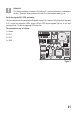
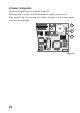
Figure 7
T3
Q1
C3
C2
C15
C14
IC1
R1
X2
SW2
BUZ1
R3
R6
R7
X1
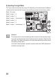
T3
Q1
C15
C14
R23
X13
C1
1
2
3
4