
User manual


35
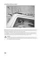
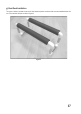
b) Inspecting the Rudder System
Figure2showstherudder(1),theattachmentscrewsoftherudder(2),therodconnectionforthelinkagerods(3),the
connectionofthewatercooling(4)andtheentryopeningsofthewatercooling(5).
Switch your remote control on and put the steering servo to the neutral position. Adjust the rudder in the neutral posi-
tion as well.
Nowfastenthelinkagerodswiththehexagonsocketscrewofthelinkageconnection(3).
Check the function of the rudder linkage. For this, observe the notes in the following chapter "Commissioning of the
Model".Finally,thehoseforwatercooling(4)mustbepushedon.
Checktheruddersystemanditslinkagefortighttanddamagebeforeanyvoyage.Adamagedorloose
linkage/attachment(e.g.loosescrews,seegure2,items2and3)mustberepairedbeforethevoyage.If
this is not observed, the linkage rods and/or rudder system may come loose unintended in operation.
Thereisadangeroffurtherdamagetoyourmodel(e.g.thesteeringservoblocks).Themodelwillalsono
longer be controllable and may cause uncontrollable damage there. Also observe the following notes in
chapter 9.
"Metal/metal" screw connections must be secured against unintended loosening either with so-called stop
nuts or with a drop of thread locker varnish.
Figure 2