
Instructions


10
11. Setting up the Receiver
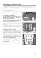
a) Receiver Connection
The receiver offers the possibility of connecting 3 servos (re-
ceiveroutput CH1, CH2, CH3)and one rechargeable receiver
battery(Bind/VCC).TheconnectionsareintendedforFutaba
plugs protected against polarity reversal and can also be used
with JR plugs if required.
When connecting servos and speed controllers, always make
sure of correct polarity of the plug connectors.
Theplug-inconnectionforthepositivelead(yellow,whiteoror-
ange, depending on the manufacturer) must be connected to the
inner(left)pincontact.Theplug-inconnectionforthenegative
lead (black or brown, depending on the manufacturer) must be
connected to the outer (right) pin contact.
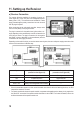
Depending on the model for which you use the remote control system, the servo and power supply connection of the
receiver can be carried out in different ways:
Figure 6
Output Output combustion model
(connection chart gure 6 A)
Electro model with speed controller
(connection chart gure 6 B)
CH1 Steering servo Steering servo
CH2 Throttle/brake servo Speed controller
CH3 Channel 3 * Channel 3 *
BIND / VCC Battery box/rechargeable receiver battery **
* Sincethetransmittersupportsnoother controlchannelsthanthosefordriveandsteeringfunctions, theCH3
output of the receiver is not used.
** Forelectricmodelswithelectronicspeedcontroller,aseparaterechargeablereceiverbatteryisonlyrequiredon
the„Bind/VCC“connectionifthespeedcontrolleruseddoesnothaveaBEC.Forfurtherinformation,refertothe
technical documents of the speed controller unit.
Figure 5