Notice d’emploi Télécommande « GT2 EVO » 2,4 GHz N° de commande 1302221
Table des matières Page 1. Introduction...........................................................................................................................................................3 2. Explication des symboles.....................................................................................................................................3 3. Utilisation conforme..............................................................................................................................
1. Introduction Chère cliente, cher client, Nous vous remercions de l‘achat du présent produit. Le produit est conforme aux exigences des normes européennes et nationales en vigueur. Afin de maintenir l‘appareil en bon état et d‘en assurer un fonctionnement sans danger, l‘utilisateur doit impérativement respecter le présent mode d‘emploi ! Le présent mode d‘emploi fait partie intégrante du produit. Il contient des consignes importantes pour la mise en service et la manipulation du produit.
3. Utilisation conforme La télécommande à 2 canaux « GT2 EVO » est exclusivement réservée à une utilisation privée dans le domaine du modélisme en liaison avec les durées de fonctionnement inhérentes. Ce système n’a pas été conçu pour un usage industriel, par ex. pour la commande de machines ou d’installations. Toute utilisation autre que celle stipulée ci-dessus provoque l’endommagement du présent produit, ainsi que des risques de courts-circuits, d’incendie, d’électrocution, etc.
6. Consignes de sécurité Tout dommage résultant du non-respect du présent mode d’emploi entraîne l’annulation de la garantie ou garantie légale. Nous déclinons toute responsabilité pour les dommages consécutifs ! De même, nous déclinons toute responsabilité pour les dommages matériels ou corporels résultant d’une utilisation de l’appareil non conforme aux spécifications ou du non-respect des présentes consignes de sécurité ! De tels cas entraînent l’annulation de la garantie ou garantie légale.
b) Fonctionnement • Si vous ne disposez pas encore de connaissances suffisantes à propos de la manipulation de modèles réduits télécommandés, veuillez vous adresser à un modéliste expérimenté ou à un club de modélisme. • Lors de la mise en service, allumez toujours d’abord l’émetteur. Vous pouvez ensuite allumer le récepteur dans le modèle réduit.
. Remarques spécifiques aux piles et batteries • Tenir les piles et batteries hors de portée des enfants. • Ne laissez pas traîner les piles et batteries, les enfants ou les animaux domestiques risqueraient de les avaler. En tel cas, consultez immédiatement un médecin ! • Ne court-circuitez ni ne démontez jamais les piles et batteries et ne les jetez pas dans le feu.
9.
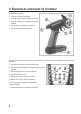
10. Mise en service de l’émetteur Dans la suite du mode d’emploi, les chiffres dans le texte se rapportent toujours à la figure placée à côté du texte ou aux figures à l’intérieur de la section. Les renvois aux autres figures seront marqués des numéros de figures correspondants. a) Insertion des piles Pour l’alimentation en courant de l’émetteur, vous devez employer 4 piles alcalines (par ex. référence Conrad 652507, pack de 4, prière de commander 1 unité) de taille AA / Mignon.
11. Mise en service du récepteur a) Raccordement du récepteur Le récepteur vous offre la possibilité de raccorder 3 servos (sortie du récepteur CH1, CH2, CH3) et une batterie du récepteur (Bind / VCC). Les raccordements sont prévus pour des connecteurs Futaba protégés contre l’inversion de polarité et peuvent, au besoin, également être utilisés avec des connecteurs JR. Lors du raccordement des servos et des régulateurs de vitesse, respectez systématiquement la polarité des connecteurs.
Attention ! Si vous employez encore un régulateur de vitesse mécanique muni d’une fiche BEC, cette dernière ne doit en aucun cas être employée pour l’alimentation électrique du récepteur. La tension disponible sur cette fiche est trop élevée. Employez plutôt une alimentation électrique distincte avec quatre piles ou une batterie du récepteur à 4 ou 5 cellules. Allumez l’émetteur puis mettez en service le récepteur.
. Montage des servos Le montage d’un servo (1) dépend toujours du modèle réduit employé. Pour de plus amples informations, consultez la documentation du modèle réduit. De manière générale, efforcez-vous toutefois de visser les servos de façon à amortir les vibrations. Pour cela, des passe-fils en caoutchouc (2) avec des cosses en métal (3) sont généralement fournis avec les servos. En cas de grippage des articulations, les servos ne peuvent pas se déplacer dans la position requise.
a) Réglage du compensateur de direction Appuyez et maintenez le bouton de trim du bas (-) pour le compensateur de direction enfoncée (voir également figure 2, n° 12). Après un certain temps, l’indicateur à DEL verte (voir également figure 2, n° 8) commence à clignoter. Lorsque le système de réception est allumé, le levier du servo tourne progressivement de la position médiane jusqu’à la fin de la plage de compensation.
. Contrôle des fonctions de direction et de conduite Raccordez maintenant les servos et régulateurs de conduite employés avec votre modèle réduit et raccordez l’alimentation électrique au récepteur. Pour une meilleure compréhension, la fonction de direction est expliquée à l’exemple d’un modèle réduit de voiture.
Attention ! La manœuvre du volant sur l’émetteur ne nécessite pas beaucoup de force. Il est donc parfaitement possible de manœuvrer le volant avec le bout des doigts. Si vous continuez de tourner le volant après avoir atteint la butée finale, cela peut détruire le mécanisme de direction à l’intérieur de l’émetteur.
b) Contrôle et réglage de la fonction de conduite Si vous tirez le levier de commande pour la fonction de conduite (voir figure 1, n° 3) jusqu’à la butée en direction de la poignée, le modèle réduit doit accélérer (voir figure 13, croquis A). Si le levier est à nouveau poussé vers l’avant, le modèle réduit doit freiner ou passer en marche arrière (voir figure 13, croquis B).
15. Fonction Failsafe Votre récepteur de radiocommande vous permet de déplacer le servo d’accélération ou le régulateur de vitesse électronique dans une position définie ou en position d’arrêt lorsqu’il s’avère impossible de recevoir un signal correct de la télécommande en présence d’un défaut.
16. Activation du codage numérique L’émetteur vous permet de piloter le récepteur avec les codages numériques « AFHDS » et « AFHDS2A ». L’émetteur a été programmé en usine pour le récepteur à codage « AFHDS2A » fourni. Si vous souhaitez utiliser un récepteur REELY à codage numérique « AFHDS », vous devez d’abord modifier le réglage de l’émetteur puis appairer le récepteur et l’émetteur (voir chapitre suivant).
17. Fonction Binding Afin que l’émetteur et le récepteur fonctionnent ensemble, ils doivent être connectés l’un à l’autre par le même codage numérique. À la livraison, l’émetteur et le récepteur se synchronisent et peuvent immédiatement être utilisés. Dans certains cas, l’appairage doit être renouvelé après avoir remplacé l’émetteur ou le récepteur ou pour réaliser un dépannage.
18. Fonction du simulateur Le cas échéant, vous pouvez également utiliser l’émetteur à des fins de simulation ou pour des jeux. En tel cas, vous devez employer le câble USB disponible en option (n° de commande Conrad 517956) ainsi qu’un logiciel approprié pour l’ordinateur (jeux de course automobile, etc.). Le branchement du câble USB s‘effectue sur la prise interface PC (voir figure 1, n° 5).
20. Élimination des déchets a) Produit Les appareils électroniques sont des matériaux recyclables et ne doivent pas être éliminés avec les ordures ménagères. À la fin de sa durée de vie, mettez l’appareil au rebut conformément aux dispositions légales en vigueur. Retirez les piles / accus éventuellement insérés et éliminez-les séparément du produit.
. Dépannage Bien que cette télécommande soit à la pointe du développement technique, il est possible que des dysfonctionnements ou des pannes surviennent. C’est pourquoi nous décrivons ci-dessous comment éliminer vous-même d’éventuels défauts. Problème Solution L’émetteur ne réagit pas • Contrôler les piles de l’émetteur. • Contrôler la polarité des piles. • Contrôler l’interrupteur de fonctionnement. Les servos ne réagissent pas • Contrôler les piles ou les batteries du récepteur.
. Caractéristiques techniques a) Émetteur Fréquence d‘émission ��������������������������������������2,4055 - 2,475 GHz Puissance d’émission ���������������������������������������<20 dBm Sortie du signal �������������������������������������������������Prise jack 3,5 mm (PPM) Tension de service ��������������������������������������������6 V/CC au moyen de 4 piles AA / Mignon Dimensions (Lx H x P) ��������������������������������������160 x 210 x 95 mm Poids avec piles �����������������������������������
Ceci est une publication de Conrad Electronic SE, Klaus-Conrad-Str. 1, D-92240 Hirschau (www.conrad.com). Tous droits réservés, y compris de traduction. Toute reproduction, quelle qu‘elle soit (p. ex. photocopie, microfilm, saisie dans des installations de traitement de données) nécessite une autorisation écrite de l‘éditeur. Il est interdit de le réimprimer, même par extraits. Cette publication correspond au niveau technique du moment de la mise sous presse. Copyright 2018 by Conrad Electronic SE.