Part Numbers: Installation Instructions 26002 REESE Dual Cam HP High-Performance Sway Control DEALER/INSTALLER: DUAL CAM HP ASSEMBLED (1) Provide this Manual to end user Equipment Required: Fastener Kit: 100126 Wrenches: 1-1/2” Open End, ¾” Open End ½” Open End, ¾” Socket & Ratchet Drill Bits: 7/16”, 17/32” & Center Drill (Pilot Drill) Other: 8 – 10” C-Clamp, Tape Measure, Light Penetrant Oil END USER: (1) Read and follow this Manual every time you use Dual Cam HP.
Installation Instructions REESE Dual Cam HP High-Performance Sway Control INSTALLATION 1. Locate both hanger brackets included in the kit (item 2, figure 1). Install U-bolt and chain from your Weight Distribution Kit on each hanger bracket as shown in figure 3 (if installing Dual Cam HP on an existing weight distribution kit, the U-bolts and chains will need to be removed from each spring bar before they can be installed on the hanger brackets).
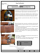
Installation Instructions REESE Dual Cam HP High-Performance Sway Control 5. Using a C-clamp suitable to accommodate your trailer frame height and the Dual Cam HP frame plate, temporarily clamp the Dual Cam HP cam arm assembly to the trailer frame and Dual Cam HP frame plate as shown in figure 6 for Trunnion style Weight Distribution kits, for Round Bar style Weight Distribution Kits, follow the dimensions in figure 7. 6.
Installation Instructions REESE Dual Cam HP High-Performance Sway Control Round Bar Set Up Locations (Standard Coupler) Approximate desired working range on a 6” tall frame. 12”-13” Figure 7 – Cam Arm Approximate Location for Round Bar Weight Distribution kits Round Bar Set up Locations (Bottom Mounted Coupler) Approximate desired working range on a 6” tall frame.
Installation Instructions REESE Dual Cam HP High-Performance Sway Control FOLLOW THE SAME MEASUREMENTS FOR THIS ORIENTATION AS SHOWN IN FIGURE 6 OR 7. Figure 8 PRE-INSTALLATION (TOW VEHICLE MAY NOT BE PRESENT) 1. If the tow vehicle is not available at the time of installation of the Dual Cam HP system, position the yolk centered on the threads of the cam arm (Approximately 2” from either end of the threaded portion of the cam arm. Run the adjustment nut down to meet the yolk.
Installation Instructions REESE Dual Cam HP High-Performance Sway Control 2. Install the spring bars into the ball mount head. Position the spring bar over the cam portion of the cam arm. 3. Install the Hanger Bracket (with the ends of the u-bolts facing inward) and Chain onto the cam by slipping the keyed slot of the hanger bracket over the button end of the cam arm (figure 9).
Installation Instructions REESE Dual Cam HP High-Performance Sway Control 2. Drill (2) 7/16” holes in each side of the frame where the punched center marks were made. The use of a center drill or small pilot hole may be very helpful prior to final drilling. 3. Install (2) supplied ½-13 Thread Forming Screws (Item 3, figure 1). Repeat for opposite side and torque (4) ½-13 Thread Forming Screws to 50 ft-lb. 4.
Installation Instructions REESE Dual Cam HP High-Performance Sway Control CAM ARM ADJUSTMENT 1. Be sure that the truck and trailer are adjusted properly per the instructions for your Weight Distribution Hitch, pull forward far enough to be sure the truck and trailer are in a straight line. (Picking a point at a distance away from the vehicle (about 100 yards) drive forward toward that point keeping the steering perfectly straight until the truck and trailer are perfectly in a straight line.) 2.
Installation Instructions Snap Up Bracket TOOLS NEEDED: Drill Bits: 7/16”, 9/16” & ¼” WARNING: Read all instructions before installing the additional bolt. Failure to follow all of these instructions may result in death or serious injury! •Installation of an additional bolt into the snap up bracket when using a Jayco RV with a coupler mounted to the bottom of the frame. 2-1/4” •If a hole does not already exist, mark the location of the hole to be drilled into the snap up bracket.
Installation Instructions REESE Dual Cam HP High-Performance Sway Control NOTES: LIMITED LIFETIMEWARRANTY 1. Limited Warranty. Cequent Performance Products, Inc. (“We” or “Us”) warrants to the original consumer purchaser only (“You”) that the product will be free from material defects in both material and workmanship for lifetime of the product, ordinary wear and tear excepted; provided that installation and use of the product is in accordance with product instructions.
Instructions d’installation Numéro de pièce : 26002 REESE Dual Cam HP Stabilisateur haute performance CONCESSIONNAIRE/INSTALLATEUR : (1) Remettre ce Manuel à l'utilisateur final. DUAL CAM HP ASSEMBLÉ UTILISATEUR FINAL : Équipement requis : (1) Lire et observer les instructions de ce Manuel à chaque utilisation Trousse de visserie : 100126 du Dual Cam HP. Clés : Clés ouvertes 1-1/2” et ¾” (2) Conserver ce manuel pour consultation ultérieure.
Instructions d’installation REESE Dual Cam HP Stabilisateur haute performance INSTALLATION 1. Repérer les deux ferrures de support incluses dans l'ensemble (article 2, figure 1).
Instructions d’installation REESE Dual Cam HP Dispositif de stabilisation du roulis haute performance 5. À l'aide d'une bride en C proportionnée à la hauteur du cadre de remorque et à la plaque de cadre du Dual Cam HP, fixer temporairement le bras de came Dual Cam HP au cadre de remorque et à la plaque de cadre Dual Cam HP, comme illustré à la figure 6 (ensemble de répartition de charge de type à tourillons) ou à la figure 7 (ensemble de répartition de charge à barres rondes). 6.
Instructions d’installation REESE Dual Cam HP Dispositif de stabilisation du roulis haute performance Positionnement pour le type à barres rondes (Coupleur standard) Orientation de la plaque de cadre En haut et en bas, la chaîne doit être la plus droite possible.
Instructions d’installation REESE Dual Cam HP Stabilisateur haute performance Orientation facultative de la plaque de cadre RESPECTER POUR CETTE ORIENTATION LES MÊMES MESURES QUE CELLES INDIQUÉES À LA FIGURE 6 OU 7. Figure 8 PRÉ-INSTALLATION (VÉHICULE PEUT ÊTRE ABSENT) 1. Si le véhicule de remorquage n’est pas disponible au moment de l’installation du système Dual Cam HP, centrer la fourche sur les filets du bras de came (environ 5 cm [2 po] de l’une des parties filetées du bras de came.
Instructions d’installation REESE Dual Cam HP Stabilisateur haute performance 2. Installer les barres stabilisatrices dans la tête du montage de boule. Placer la barre stabilisatrice au-dessus de la partie "came" du bras de came. 3. Poser la ferrure de support (avec les extrémités des boulons en U orientés vers l'intérieur) et la chaîne sur la came en faisant glisser la fente en forme de poire de la ferrure au-dessus de l'extrémité à boutons du bras de came (figure 9).
Instructions d’installation REESE Dual Cam HP Stabilisateur haute performance 2. Percer deux (2) trous 7/16 po dans chaque côté du cadre où les trous ont été marqués. L'utilisation d'un foret à centrer ou d'un petit trou pilote peut s'avérer très utile avant le perçage final. 3. Poser deux (2) vis à formage de filet ½-13 fournies (article 3, figure 1). Répéter du côté opposé et serrer les quatre (4) vis à formage de filet ½-13 au couple de 50 lb-pi. 4.
Instructions d’installation REESE Dual Cam HP Stabilisateur haute performance AJUSTEMENT DU BRAS DE CAME 1. S'assurer que le véhicule et la remorque sont réglés correctement d'après les instructions de l'attelage à répartition de charge, tirer suffisamment vers l'avant pour que véhicule et remorque se trouvent en ligne droite.
Instructions d’installation Support encliquetable OUTILS REQUIS : Mèches : 7/16”, 9/16” et ¼” AVERTISSEMENT : Veuillez lire toutes les instructions avant de poser un boulon supplémentaire. L'omission d'observer toutes les instructions peut causer des blessures sévères, voire la mort ! •Pose d'un boulon supplémentaire dans le support encliquetable. 2-1/4” •Marquer l'emplacement du trou à percer dans le support encliquetable.
Instructions d’installation REESE Dual Cam HP Stabilisateur haute performance REMARQUES : GARANTIE À VIE LIMITÉE 1. Garantie limitée. Cequent Trailer Products, Inc. (“Nous”) garantit à l’acheteur initial seulement (“Vous”) que le produit sera exempt de vices de matériaux et de fabrication pendant la durée de vie du produit, exception faite de l’usure normale, dans la mesure où l’installation et l’utilisation du produit sont conformes aux instructions accompagnant celui-ci.
Instrucciones de instalación Números de partes: 26002 Sistema REESE Doble Leva HP Control de oscilación de Alto Desempeño SISTEMA DOBLE LEVA HP ENSAMBLADO CONCESIONARIO/INSTALADOR: Equipo necesario: Kit de tornillos: 100126 Llaves: Extremo abierto 1-1/2", extremo abierto 3/4" Extremo abierto ½”, tubo y trinquete 3/4" Brocas de taladro: 7/16”, 17/32” y taladro central (taladro piloto) Otros: Abrazadera en C 8 – 10”, cinta de medir, aceite ligero penetrante (1) Entregue este manual al usuario final.
Instrucciones de instalación Sistema REESE Doble Leva HP Control de oscilación de Alto Desempeño INSTALACIÓN 1. Localice ambos soportes colgantes que se incluyen en el kit (pieza 2, figura 1).
Instrucciones de instalación Sistema REESE Doble Leva HP Control de oscilación de Alto Desempeño 5.
Instrucciones de instalación Sistema REESE Doble Leva HP Control de oscilación de Alto Desempeño Puntos de instalación estilo Barra Redonda (Acoplador estándar) ORIENTACIÓN DE LA PLACA DEL BASTIDOR LA CADENA DEBE ESTAR LO MÁS RECTA POSIBLE DESDE LA MARCA EN EL ACOPLADOR A LO LARGO DEL COSTADO DEL DEL BASTIDOR Figura 7 – Ubicaciones aproximadas del brazo de leva para kits de distribución de peso estilo Barra Redonda Puntos de instalación de Barra Redonda (Acoplador de montaje inferior) LA CADENA DEBE
Instrucciones de instalación Sistema REESE Doble Leva HP Control de oscilación de Alto Desempeño Orientación opcional de la placa del bastidor SIGA LAS MISMAS MEDIDAS PARA ESTA ORIENTACIÓN COMO SE MUESTRA EN LA FIGURA 6 Ó 7. Figura 8 PRE-INSTALACIÓN (VEHÍCULO DE REMOLQUE PODRÍA NO ESTAR PRESENTE) 1.
Instrucciones de instalación Sistema REESE Doble Leva HP Control de oscilación de Alto Desempeño 2 Instale las barras de resorte dentro de la cabeza de montaje esférico. Coloque la barra de resorte sobre la porción de leva del brazo de leva. 3. Instale el soporte colgante (con los extremos de los pernos en U orientados al interior) y la cadena sobre el sistema de leva deslizando la ranura con chaveta del soporte colgante sobre el extremo inferior del brazo de leva (figura 9).
Instrucciones de instalación Sistema REESE Doble Leva HP Control de oscilación de Alto Desempeño 2. Perfore (2) orificios de 7/16” en cada lado del bastidor donde se hicieron las marcas de perforación. Podría ser de utilidad usar un taladro central o pequeño orificio piloto antes de la perforación final. 3. Instale (2) tornillos de rosca formante de ½-13 que se suministran (pieza 3, figura 1). Repita para el lado opuesto y apriete a torsión (4) tornillos de rosca formante de ½-13 a 50 pies-lbs. 4.
Instrucciones de instalación Sistema REESE Doble Leva HP Control de oscilación de Alto Desempeño AJUSTE DEL BRAZO DE LEVA 1. Verifique que el vehículo y el remolque se ajusten correctamente según las instrucciones para su enganche de distribución de peso, empuje hacia el frente lo suficiente para verificar que el vehículo y el remolque estén en línea recta.
Instrucciones de instalación HERRAMIENTAS NECESARIAS: Soporte de agarre Brocas: 7/16”, 9/16” y ¼” ADVERTENCIA: Lea todas las instrucciones antes de instalar el perno adicional. ¡No seguir estas instrucciones podría resultar en la muerte o lesión de gravedad! •Instalación de un perno adicional en el soporte de agarre. 2-1/4” •Marque la localización del orificio a perforar dentro del soporte de agarre. Centre el orificio de izquierda a derecha y colóquelo 2-1/4” por encima del arco en el soporte.
Instrucciones de instalación Sistema REESE Doble Leva HP Control de oscilación de Alto Desempeño NOTAS: GARANTÍA LIMITADA DE POR VIDA 1. Garantía limitada. Cequent Performance Products, Inc.