
User Manual


2. Drill (2) 7/16” holes in each side of the frame where the punched center marks were made. The use of a center drill or small
pilot hole may be very helpful prior to final drilling.
3. Install (2) supplied ½-13 Thread Forming Screws (Item 3, figure 1).
Repeat for opposite side and torque (4) ½-13 Thread Forming Screws to 50 ft-lb.
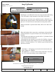
4. Install ½-13 Hex Nut (Jam Nut)onto the ½-13 X 3 ½” Square Head Bolts and Install into the frame brackets as shown in figure 11.
5. Tighten the Set Screw until it contacts the trailer frame. Then proceed to tighten ¼ to ½ turn (DO NOT OVERTIGHTEN SET
SCREW). Tighten the Jam Nut preventing the set screw from backing out while in use. Repeat for other side of trailer frame.
6. Remove C-Clamps from frame.
© 2010 Cequent Performance Products, Inc.
Sheet 7 of 30 26002IN 09/03/13 Rev. N
Form: F205 Rev A 5-6-05
Installation Instructions
REESE Dual Cam HP
High-Performance Sway Control
C-CHANNEL DUAL CAM HP FRAME PLATE INSTALLATION
NOTE: Some C-Channel frames may have square outside corners that do not allow the frame plate to contact the
bottom of the frame. For these type of frames a ½” flat washer (Not Supplied) is required between the outside of the
trailer frame and the frame plate. The bottom of the frame plate MUST contact the bottom of the trailer frame.
1. With the C-clamps still in place, center punch (2) holes in the frame for each bracket.
2. Drill (2) 17/32” holes in each side of the frame where the punched center marks were made. The use of a center drill or small
pilot hole may be very helpful prior to final drilling.
3. Install the (2) supplied ½-13 x 1 ½” Bolts, ½” Lock Washers & ½” Nuts (items 5,6 & 7) figure 12.
Repeat for opposite side and torque (4) ½-13 Bolts to 85 ft-lb.
4. Install ½-13 Hex Nuts onto the ½-13 X 3 ½” Square Head Bolts and
install into the frame brackets as shown in figure 13.
5. Tighten the Set Screw until it contacts the trailer frame.
Then proceed to tighten ¼ to ½ turn (DO NOT OVERTIGHTEN
SET SCREW). Tighten the Jam Nut preventing the set screw
from backing out while in use. Repeat for other side of trailer frame.
6. Remove C-Clamps from frame.
Figure 13
SET SCREW
JAM NUT
NUT
LOCK
WASHER
HEX HEAD
BOLT
Figure 11
SET SCREW
JAM NUT
FRAME
BRACKET
FLANGE HEAD,
THREAD
FORMING
SCREWS