Style that revolves around you. • CEILING FAN OWNER’S MANUAL • • BIMINI • 9/06 SUITABLE FOR USE IN WET LOCATION WARNING: Read and follow these instructions carefully and be mindful of all warnings shown throughout.
GENERAL INSTALLATION & OPERATION INSTRUCTIONS IMPORTANT SAFEGUARDS: 1. To ensure the success of the installation, be sure to read the instructions and review the diagrams thoroughly before beginning. 2. To avoid possible electric shock, be sure electricity is turned off at the main power box before wiring. All electrical connections must be made in accordance with local codes, ordinances, and/or the National Electric Code.
IMPORTANT SAFETY PRECAUTIONS Thank you for choosing a Regency Ceiling Fan. You have chosen the best! Your new ceiling fan has been designed to provide many years of service and enjoyment. WARNINGS: * Disconnect power by removing fuse or turning off circuit breaker before installing the fan. * To reduce the risk of fire, electrical shock, or personal injury, mount only to the building’s structure.
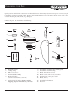
UNPACKING YOUR FAN Unpack your fan and check the contents. Do not discard the carton. If warranty replacement or repair is ever necessary, the fan should be returned in original packing. Remove all parts and hardware. Do not lay motor housing on its side, as the decorative housing may shift, bend, or get damaged. Examine all parts. You should have the following: 5 1 12 2 14 3A 6 13 3 7 8 4 9 10 11 15 1. 2. 3A. 3. 4.
PREPARATION Parts identification on assembled fan Canopy Downrod Collar cover Blade Blade Arm Verify that you have all parts before beginning the installation. Check foam insert closely for missing parts. Remove motor from packing. To avoid damage to finish, assemble motor on soft padded surface or use the original foam inset in motor box. Do not lay fan on its side as this could result in shifting of motor in decorative enclosure.
ASSEMBLY OF DOWNROD SYSTEM ATTACHING DOWNROD, CANOPY AND COLLAR COVER (FIG. 2): 1. Carefully support fan body (motor) in its styrofoam packing with the mounting collar (where the wires come out) facing upward. 2. Remove ball from downrod by loosening set screw in the side of the ball. Slide ball down and remove ball pin; remove ball. 3.
INSTALLING THE FAN 1. Be sure your hanger bracket is secure. The entire weight of the fan will now be hanging from it. 2. Lift fan body/downrod/ball assembly into hanger bracket opening. NOTE: The tab in hanger bracket opening should fit into slot on ball (Fig. 3). Hanger bracket tab 3. Make wire connections, (refer to section titled “Electrical Connections”page 6) Ball slot 4. Slide canopy up and fasten to hanger bracket with screws provided AFTER all electrical connections are complete.
BLADE ATTACHMENT BLADE ATTACHMENT: 1. Place washer on screw. Insert this assembly through the blade and start the screw into the blade arm. Repeat this procedure without tightening the screw until all screws have been started into the blade arm. (Fig. 4). 2. Tighten all screws. Repeat for remaining blade arms/blades. 3. Fasten blade assembly to motor with screws and washers provided. Repeat procedure for remaining blades (Fig. 5).
INSTALLATION OF DETACHABLE SWITCH HOUSE MONTING HUB 1. Remove one of the three screws on the mounting hub located on the fan motor. 2. Loosen the other two screws three to four revolutions. 3. Install detachable switch housing mounting hub to switch housing hub. 4. Pass the 9 pin connector through the center hole of the detachable swith housing mounting hub. 5. Line up the two slotted holes with the two loose screws on the mounting hub located on fan motor. 6.
INSTALLATION OF REMOVABLE SWITCH HOUSING NOTE: Be sure the power is off before installing. 1. Loosen the 3 side screws on switch housing hub halfway. 2. If installing light kit, carefully remove light kit plug in bottom of switch housing. Attach light kit to switch housing per instructions supplied with light kit. See “Electrical Connections” for hook-up of light kit. 3. Connect the plug and receptacle and make sure side buckle snaps in place. 4. Attach the switch housing to the switch housing hub.
REMOTE CONTROL GENERAL INFORMATION Multiple code choices are included with your fan’s remote control in case: • you have more than one remote control fan and want them to respond only to their own remote control • you have other radio controlled devices in your home that may interfere with the fan remote control (i.e. garage door opener) • you experience radio interference on a chosen frequency (code setting) NOTE: Factory code settings should not be used.
OPERATION OPERATING BUTTONS ON THE TRANSMITTER HI – fan high speed MED – fan medium speed LOW – fan low speed OFF – fan speed off LIGHTS – light brightness and off function • The light functions are controlled by pressing the light button. Tap button quickly to turn light off or on. Push the button once and release to turn the light on to full brightness. Hold the button down to increase or decrease light brightness.
CARE AND CLEANING Periodically it may be necessary to re-tighten blade to blade arm screws or blade arm to motor screws to prevent clicking or humming sound during operation. This is especially true in climates with broad temperature and humidity ranges. When dusting the blades, you must support the blade to prevent bending - no pressure should be applied to the blades. If you experience any flaws in the operation of your fan, please check the following points.
THANK YOU FOR PURCHASING A REGENCY CEILING FAN. Write to us at: Regency Ceiling Fans P.O. Box 730 Fenton, MO 63026 For additional troubleshooting tips, visit us on the Web at: www.regencyfan.