www.regency-fire.com P33R Zero Clearance Rear Direct Vent Gas Fireplace MODELS: P33R-NG2 Natural Gas Owners & Installation Manual P33R-LP2 Propane WARNING: FOR YOUR SAFETY If the information in these instructions are not followed exactly, What to do if you smell gas: a fire or explosion may result causing property damage, Do not try to light any appliance personal injury or loss of life. Do not touch any electrical switch: do not use any phone in your FOR YOUR SAFETY building.
To the New Owner: Congratulations! You are the owner of a state-of-the-art Gas Stove by FIREPLACE PRODUCTS INTERNATIONAL. The P33R-2 is a hand crafted appliance and has been designed to provide you with all the warmth and charm of a wood fireplace at the flick of a switch. The model P33R-2 has been approved by Warnock Hersey for both safety and efficiency. As it also bears our own mark, it promises to provide you with economy, comfort and security for many trouble free years to follow.
TABLE OF CONTENTS Safety Label Safety Label ............................................................... 4 Installation Important Message .................................................... 5 Before You Start ........................................................ 5 General Safety Information ......................................... 5 Manufactured Home Additional Requirements ............ 5 Installation Checklist .................................................. 6 Unit Dimensions ....................
SAFETY LABEL This is a copy of the label that accompanies each P33R-2 Zero Clearance Direct Vent Gas Fireplace. We have printed a copy of the contents here for your review. The safety label is located on the front inside base of the unit, visible when the bottom louver is open. NOTE: Regency units are constantly being improved. Check the label on the unit and if there is a difference, the label on the unit is the correct one.
INSTALLATION IMPORTANT: SAVE THESE INSTRUCTIONS YOUNG CHILDREN SHOULD BE CAREFULLY SUPERVISED WHEN THEY ARE IN THE SAME ROOM AS THE APPLIANCE. The P33R-NG2 or P33R-LP2 Direct Vent Fireplace must be installed in accordance with these instructions. Carefully read all the instructions in this manual first. Consult the "authority having jurisdiction" to determine the need for a permit prior to starting the installation.
INSTALLATION INSTALLATION CHECKLIST UNIT DIMENSIONS 1) Locate appliance a) Room location, page 6 b) Clearances to Combustibles, page 6 c ) Mantle Clearances, page 7 d) Framing & Finishing Requirements, page 8 e) Venting Requirements, pages 10 to 15. 5) This appliance is Listed for bedroom installations when used with a Listed Millivolt Thermostat. Some areas may have further requirements, check local codes before installation.
INSTALLATION CLEARANCES COMBUSTIBLE MANTELS The clearances listed below are Minimum distances unless otherwise stated: Because of the extreme heat this fireplace emits, the mantel clearances are critical. Combustible mantel clearances from top of unit are shown in the diagram below. A major cause of chimney related fires is failure to maintain required clearances (air space) to combustible materials.
INSTALLATION FRAMING AND FINISHING 1) Determine the total thickness of facing material (e.g. drywall plus ceramic tiles) to allow the finished surface to be flush with the front of the unit. Total facing thickness can vary from 1/2" (13mm) to 1-1/4" (32mm) thick. Rear Termination Install Side Nailing Strips, and Top Facing Support before unit is slipped into position. See page 9 for assembly details.
INSTALLATION UNIT ASSEMBLY PRIOR TO INSTALLATION The Top Facing Support, the Side Nailing Strips and the 2 Top Standoffs must be correctly positioned and attached to the top before unit is slipped into position. Top Standoff Assembly The top standoffs are shipped in a flat position and must be pulled up and bent into the correct shape. Setup each of the 2 Top Standoff by bending up at the bend lines until the screw hole in the standoff and the pre-punched screw holes on the top line up.
V E V M V B Vent terminal . F V V A G B C V A V B B V A K B H j N V Area where terminal is not permited A V 18" L A Note: - A vent shall not terminate directly above a sidewalk or paved driveway which is located between two single family dwellings and serves both dwellings. - Only permitted if veranda, porch, deck, or balcony is fully open on a minimum of two sides beneath the floor. - If the vent termination is accessible, a certified guard shall be installed.
INSTALLATION VENTING INTRODUCTION The P33R-2 uses the "balanced flue" technology Co Axial system. The inner liner vents products of combustion to the outside while the outer liner draws outside combustion air into the combustion chamber thereby eliminating the need to use heated room air for combustion and losing warm room air up the chimney.
INSTALLATION INSTALLATION PROCEDURES for Regency Direct Vent System (Flex) 1) Locate the unit in the framing, rough in the gas (preferably on the right side of the unit) and the electrical (Junction block is on the left side) on the left. Locate the centerline of the termination and mark wall accordingly. Cut a 10"(254mm) hole in the wall (inside dimension).
INSTALLATION SIMPSON DURA-VENT VENTING Horizontal or Vertical Terminations The Simpson Dura-Vent Direct Vent System offers a complete line of component parts for installation of both horizontal and vertical installations. Many items are offered in decorative black, as well as galvanized finish. We recommend using the galvanized finish for installation with the P33R-2.
INSTALLATION VENTING ARRANGEMENTS - HORIZONTAL TERMINATIONS SIMPSON DURA-VENT DIRECT VENT GS SYSTEM or Regency Direct Vent (Flex) for Horizontal Terminations (Propane & Natural Gas) The diagram shows all allowable combinations of vertical runs with horizontal terminations, using two 90o elbows (two 45o elbows equal one 90o elbow). A vent guard should be used whenever the termination is lower than the specified minimum or as per local codes.
INSTALLATION VENTING ARRANGEMENTS - VERTICAL TERMINATIONS SIMPSON DURA-VENT DIRECT VENT GS SYSTEM (Propane & Natural Gas) The shaded area in the diagram shows all allowable combinations of straight vertical and offset to vertical terminations , using three 90o elbows (two 45o elbows equal one 90o elbow), with Simpson Dura-Vent Direct Vent GS vent systems for Propane and Natural Gas. • • • Vent must be supported at offsets Firestops are required at each floor level and whenever passing through a wall.
INSTALLATION VERTICAL TERMINATION WITH CO-LINEAR FLEX SYSTEM THE APPLIANCE MUST NOT BE CONNECTED TO A CHIMNEY FLUE SERVING A SEPARATE SOLID FUEL BURNING APPLIANCE. Masonry chimneys may take various contours which the flexible liner will accommodate. However, keep the flexible liner as straight as possible, avoid unnecessary bending. The Air Intake pipe must be attached to the inlet air collar of the termination cap.
INSTALLATION Venting Arrangements - Vertical Terminations with Co-linear Flex System for both Residential & Manufactured Homes into Masonry Fireplaces The shaded area in the diagrams show the allowable vertical terminations.
INSTALLATION HORIZONTAL INSTALLATIONS Install the vent system according to the manufacturer's instructions included with the components. b) Horizontal runs of vent must be supported every three feet. Wall straps are available for this purpose. 1) Set the unit in its desired location. Check to determine if wall studs or roof rafters are in the way when the venting system is attached. If this is the case, you may want to adjust the location of the unit.
INSTALLATION pipe into the vent cap assembly. It is important that the vent pipe extends into the vent cap sufficient distance so as to result in a minimum pipe overlap of 1-1/4 inches. Secure the connection between the vent pipe and the vent cap 3 sheet metal screws. 4) Assemble the desired lengths of pipe and elbows. Ensure that all pipes and elbow connections are in the fully twist-locked position and sealed. Dia.
INSTALLATION Important: Always check for gas leaks with a soap and water solution or gas leak detector. Do not use open flame for leak testing. PILOT ADJUSTMENT Periodically check the pilot flames. Correct flame pattern has three strong blue flames: 1 flowing around the thermopile, 1 around the thermocouple and 1 flowing across the burner (it does not have to be touching the burner). Note: If you have an incorrect flame pattern, contact your Regency dealer for further instructions.
INSTALLATION Conversion Kit from Natural Gas to Propane Model #431-969 for P33R-2 using SIT 820 NOVA Gas Valve THIS CONVERSION MUST BE DONE BY A QUALIFIED GAS FITTER IF IN DOUBT DO NOT DO THIS CONVERSION !! 7) Pull off the pilot cap to expose the pilot orifice. Conversion Kit Contains: Qty.
INSTALLATION OPTIONAL BRICK PANELS 1) Undo the bottom 2 door latches and open and remove glass door. Remove logs. 2) Attach the 2 Rear Brick Retaining clips to the rear wall. Loosen the screws in the top and rear wall of the firebox and slide the retaining clips into position (tight against the firebox top) and then tighten the screws. LOG SET INSTALLATION Read the instructions below carefully and refer to the diagrams. If logs are broken do not use the unit until they are replaced.
INSTALLATION 8) Place the embers on the front of the burner tray in the places shown on the photo. C) 02 -6 0 A) 02-57 B) 02-61 Place embers in these 3 locations on the burner tray. 6) Place the bottom left front edge of Log D) 02-58 against the left edge of the burner tray and rest the log on the cutout on Log C) 02-60. 9) Test fire to ensure proper light off (make sure flame flows smoothly from one end of burner to the other).
INSTALLATION FLUSH LOUVERS 1) Install the top louver by sliding the two bracket clips into the brackets located underneath the top of the firebox. 2) Install the bottom louver by folding the louver down and then sliding the Bottom Louver bracket down onto the 2 pins on the base of the unit (dia. 1). Secure with 1 screw as per dia. 2. Diagram 1 DOUBLE SCREEN DOOR 1) Pull out the top louver. 2) Center the screen door and hook over the flush door.
INSTALLATION BAY LOUVERS 1) Install top louver by sliding the two bracket clips into the brackets located on top of the bay door. See below. The fitted louver leaves a small gap between faceplate bottom and louver top. 5) Open the bottom louver. Pull the Burner ON/ OFF control box from inside the bottom of the fireplace and position the slots in the bracket over the 2 screws on the left side of the bottom louver. Push down to lock into place. Tighten the screws.
INSTALLATION WIRING DIAGRAM This heater does not require a 120V A.C. supply for operation. In case of a power failure, the burner switch and the optional remote control/thermostat will continue to operate. However, a 120V A.C. power supply is needed for the fan/blower operation. (Do not cut the ground terminal off under any circumstances.
INSTALLATION INSTALLING THE OPTIONAL FAN 120 Volt AC power is needed for the fan switch and blower. The fan can be hard wired if desired. The receptacle box should be installed on the left hand side of the unit by a qualified electrician. The neutral (wider) slot of the polarized receptacle should be at the top. 11) Attach the two control boxes to the bottom louver and tighten the 2 screws on the left side and 1 screw on the right side. Unit must be grounded at all times.
OPERATING INSTRUCTIONS COPY OF THE LIGHTING PLATE INSTRUCTIONS FOR YOUR SAFETY READ BEFORE LIGHTING This appliance must be installed in accordance with local codes, if any; if not, follow the current CAN1-B149/ANSI Z 223.1 (Australia: AG601, New Zealand: NZS 5261) WARNING: If you do not follow these instructions exactly, a fire or explosion may result causing property damage, personal injury or loss of life.
OPERATING INSTRUCTIONS OPERATING INSTRUCTIONS AERATION ADJUSTMENT 1) Read and understand these instructions before operating this appliance. 3) Check to ensure there are no gas leaks. The air shutter can be adjusted by moving the adjusting wire up or down. The wire is accessed through the bottom louver opening. Open the air shutter for a blue flame or close for a yellower flame. The burner aeration is factory set but may need adjusting due to either the local gas supply or altitude.
MAINTENANCE NORMAL OPERATING SOUNDS OF GAS APPLIANCES It is possible that you will hear some sounds from your gas appliance. This is perfectly normal due to the fact that there are various gauges and types of steel used within your appliance. Listed below are some examples. All are normal operating sounds and should not be considered as defects in your appliance. Blower: Regency gas appliances use high tech blowers to push heated air farther into the room.
MAINTENANCE THERMOPILE/ THERMOCOUPLE 1) Open the bottom louvers. 2) Loosen the thermocouple or thermopile with a 7/16" wrench. Flush Glass Replacement Bay Glass Replacement Remove the flush door front (as per instructions on page 23). Remove the 4 glass clips from each corner. Slide in the new replacement glass. Push the 4 glass clips back onto the frame. The glass must have gasketing around it. 1) Remove the door from the unit and place on a soft surface to prevent scratching.
MAINTENANCE REMOVING VALVE 1) Shut off the gas supply. 2) Remove the louvers (and bay door if it is on). gram 2) and then lift the entire assembly out (diagram 3). 10) Undo the pilot tube from the valve with a 7/16" wrench. INSTALLING VALVE 1) Attach the valve to the valve bracket with the 4 (m5x8 metric) screws provided. 2) Reconnect the "gas out" flare fitting with an 11/16" wrench. 3) Open the flush door and remove the door. 4) Remove the logs.
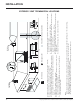
PARTS LIST Main Assembly Part # Description 1) 2) 948-247 * Door Handle Thermodisc Bracket 7) 8) 9) 10) 13) 14) 16) 17) 19) 20) 21) 22) 23) 24) 26) 27) 910-428 910-429 910-430 904-687 948-045 948-115 * * 430-129 430-031 430-032 430-010 430-001 510-010 * * Duplex Receptacle Box - Receptacle Cover - Receptacle Clamp Connector #12 Jack Chain Door Extension Spring Thermodisc Top Thermodisc Box Base Receptacle Box Mount Top Nailing Strip Side Nailing Strip Firebox Baffle Top Standoff Standoff - Side/Back
PARTS LIST Burner & Log Assembly Part # 53) 54) 55) 56) 57) 58) 59) 60) 66) 67) 68) 79) 82) 83) 85) 86) 87) Description 430-055 910-421 910-422 910-190 Gasket - Valve Access Plate - NG/LP Pilot ON/OFF Extension Knob Flame HI/LOW Extension Knob Piezo Ignitor and Nut 432-574/P 432-576/P 910-378 910-380 * * * 910-038 910-039 904-655 904-163 936-170 * W840470 431-515 430-100 * 431-930 430-097 430-098 Valve Assy - Natural Gas Valve Assy - Propane S.I.T. Valve - Natural Gas S.I.T.
PARTS LIST Flush Front & Louvers Part # Description 117) 904-196 130) 430-924 131) 430-926 430-947 Magnet - 1' round Flush Glass Trim (set) - Gold (Option) Flush Glass Trim (set) - Brass (Option) Flush Glass Trim (set) - Brushed Steel (Option) 430-918 430-920 430-922 430-923 133) * 134) * Flush Flush Flush Flush Flush Flush 135) 137) 139) 140) Louvers (set) - Gold/Black (Option) Louvers (set) - Brass/Black (Option) Louvers (set) - Black (Option) Louvers (set) - Black/Steel (Option) Louver Assy-Top Lo
PARTS LIST Bay Front & Louvers 106) 107) 108) 110) 111) 112) 117) 118) 120) Part # Description Part # Description 430-930 940-079/P 936-243 940-078/P * 902-322 432-905 432-906 * 904-196 * 400-189 Bay Front Complete Side Glass Glass Gasket Center Glass Bay Door Frame Bay Brick Panel - Standard Bay Brick Panel - Standard Brown Bay Brick Panel - Standard Red Bay Brick Panel Spacer Magnet (1" round) Louver Hold Down Glass Retainer 430-932 430-934 430-936 430-937 * * 948-042 432-960 948-216 Bay Louvers
NOTES _____________________________________________________________________________________ ____________________________________________________________ __________________________________________________________ ____________________________________________________________ _______________________________________________________ _____________________________________________________ __________________________________________________________ _________________________________________________________ ___________
NOTES _____________________________________________________________________________________ ____________________________________________________________ __________________________________________________________ ____________________________________________________________ _______________________________________________________ _____________________________________________________ __________________________________________________________ _________________________________________________________ ___________
WARRANTY Regency Fireplace Products, are designed with reliability and simplicity in mind. In addition, our internal Quality Assurance Team carefully inspects each unit thoroughly before it leaves our door. Regency Industries Ltd. is pleased to extend this limited lifetime warranty to the original purchaser of a Regency Product.
Regency fireplace products are designed with reliability and simplicity in mind. In addition, our internal Quality Assurance Team carefully inspects each unit thoroughly before it leaves our door. Fireplace Products International Ltd. is pleased to extend this Limited Lifetime Warranty to the original purchaser of a Regency Product. See the inside back cover for details. Register your Regency online at http://www.regency-fire.