
Installation manual

Regency
®
Model 4734 Access Control Expander Installation Manual (P/N 150807, Rev. A) Revised 5/98
51
6.5.2 I/O Programming Procedure-5540 Software
To program the I/O statements using the 5540 software, go to the Programmable I/O Menu (selection L of
the Edit Accounts Menu). The inputs and outputs are programmed through a series of control statements that
you enter into this menu. These statements take the form: 1 OUTPUT = STATUS.
The OUTPUT label refers to the device on which an output is generated. Output labels are assigned using
the names shown in Tables 19 and 20. The STATUS label refers to the internal condition or combination of
conditions that cause the output to be generated. STATUS labels are assigned using the names shown in
Table 21.
Some labels include a number in brackets [ ], which specifies one of several similar outputs or sets of out-
puts; or one of several components of the installation (e.g., zones), or sets of components, on which an inter-
nal condition can exist (e.g., armed or disarmed).
Some labels can be used to access eight data bits at a time. Labels of this type are identified in the Data Type
column of Tables 19 and 21 by the word BITS. To access only one of the eight bits, key in a “.” (period char-
acter) after the label, followed by a digit from 0 to 7.
Lables of data type NUMBER take the form (LABEL = NUMBER).
EXAMPLE 1: 1 RLY[1] = ALMAREA
The output label RLY[1] refers to the first group of eight outputs on the first 4180 module. The status
label ALMAREA indicates that all eight areas in alarm status bits are to be accessed.
EXAMPLE 2: 1 RLY[4].7 = AZONES[10].5
The output label RLY[4].7 refers to the eighth output (.7) on the second group of outputs on the second
4180 module ([4]). The status label AZONES[10].5 refers to the armed status of the sixth zone (.5) of
the zone group to which [10] has been assigned (zones 73-80)
—in other words, Zone 78. Table 22
shows which zones are assigned to each bracketed number.
EXAMPLE 3: 1 TER16 = (THR = 1) or (THR = 2)
The output label TER16 refers to Terminal 16 of the 4720. (THR = 1) refers to the hour that begins at
1:00 AM and ends at 1:59 AM. (THR = 2) refers to the hour that begins at 2:00 AM and ends at 2:59
AM. If the current time falls within either of these two intervals, the LED connected to Terminal 16 will
light. Because these two time periods happen to be consecutive, the LED will remain on continuously
from 1:00 AM to 2:59 AM; it will not go off between the two time intervals.
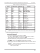
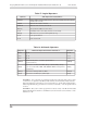
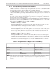
Table 19: Programmable I/O Output Labels (Read/Write)
1
Label
2
Data Type Function
RLY[1-4] BITS 4180 status relays
TER16 BIT Output on Terminal 16
TER15 BIT Output on Terminal 15
TER18 BIT Output on Terminal 18
X10[1-4] BITS X-10 output bits
SCR[1-9] NUMBER, BITS User scratch area
NOTE
1
An output can be generated (written on the left side of the statement) as a result of an internal condition
or its own status can be read (right side of statement) to generate an output on some other device.
2
In this column, the number of brackets [ ] indicates how many devices or components of this type are
available.