Regency Bellavista™ B36X Gas Fireplace Owners & Installation Manual MODEL: B36X Medium DV Gas Fireplace www.regency-fire.com FOR YOUR SAFETY WARNING: If the information in these instructions are not followed exactly, What to do if you smell gas: Do not try to light any appliance a fire or explosion may result causing property damage, Do not touch any electrical switch: personal injury or loss of life. do not use any phone in your FOR YOUR SAFETY building.
To the New Owner: Congratulations! You are the owner of a state-of-the-art Gas Fireplace by REGENCY®. The Bellavista™ B36X has been designed to provide you with all the warmth and charm of a wood fireplace at the flick of a switch. The Bellavista™ B36X has been approved by Warnock Hersey for both safety and efficiency. As it also bears our own mark, it promises to provide you with economy, comfort and security for many trouble free years to follow.
TABLE OF CONTENTS SAFETY LABEL Copy of Safety Decal .....................................................4 REQUIREMENTS MA Code - CO Detector.................................................5 DIMENSIONS Unit Dimensions ............................................................6 INSTALLATION Important Message ......................................................7 Before You Start ............................................................7 General Safety Information....................................
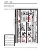
SAFETY LABEL This is a copy of the label that accompanies each Bellavista™ B36X Direct Vent Gas Fireplace. We have printed a copy of the contents here for your review. COPY OF SAFETY DECAL NOTE: Regency® units are constantly being improved. Check the label on the unit and if there is a difference, the label on the unit is the correct one. For the State of Massachusetts, installation and repair must be done by a plumber or gasfitter licensed in the Commonwealth of Massachusetts.
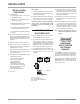
REQUIREMENTS MA Code - CO Detector (for the State of Massachusetts only) 5.08: Modifications to NFPA-54, Chapter 10 (2) Revise 10.8.
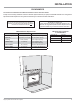
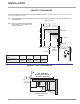
DIMENSIONS UNIT DIMENSIONS 33” (838mm) 35-1/4” (895mm) 30-3/8” (762mm) 39-1/16” (992mm) 21”(533mm) 37-1/2” (953mm) 1”(25.
INSTALLATION IMPORTANT MESSAGE SAVE THESE INSTRUCTIONS The Bellavista™ B36X Gas Fireplace must be installed in accordance with these instructions. Carefully read all the instructions in this manual first. Consult the "authority having jurisdiction" to determine the need for a permit prior to starting the installation. It is the responsibility of the installer to ensure this fireplace is installed in compliance with manufacturers instructions and all applicable codes.
INSTALLATION INSTALLATION CHECKLIST 1) Locate appliance a) Room location (Refer to "Locating Your Gas fireplace" section) b) Clearances to Combustibles (Refer to "Clearances" section) c) Mantel Clearances (Refer to "Combustible Mantel Clearances" section) 1) Clocking the appliance to ensure the correct firing rate (rate noted on label) after burning appliance for 15 minutes. 4) This appliance is Listed for bedroom installations using the standard Remote (millivolt thermostat system).
INSTALLATION CLEARANCES The clearances listed below are Minimum distances unless otherwise stated: A major cause of chimney related fires is failure to maintain required clearances (air space) to combustible materials. It is of the greatest importance that this fireplace and vent system be installed only in accordance with these instructions. Caution Requirements The top, back and sides of the fireplace are defined by standoffs.
INSTALLATION MANTEL CLEARANCES Due to the extreme heat this fireplace emits, the mantel clearances are critical. Combustible mantel clearances from top of front facing are shown in the diagram on the right. Note: A non-combustible mantel may be installed at a lower height if the framing is made of metal studs covered with a noncombustible board. Mantel Clearances 8 6 4 0 14 12 10 Note: Ensure the paint that is used on the mantel and the facing is "heat resistant" or the paint may discolour.
INSTALLATION FRAMING Framing Dimensions Description B36X M Framing Width 36 - 1/4"(921mm) N Framing Height 39 - 3/8" (1000mm) O (Rear Vent) Framing Depth - Rear Vent 20 - 3/4" (527mm) O (Top Vent) Framing Depth - Top Vent 19 - 1/2" (495mm) P (Top Vent) Corner Facing Wall Depth 48 - 5/8" (1235mm) P (Rear Vent) Corner Facing Wall Depth 53" (1346mm) AstroCapXL 61-1/2" (1562mm) - other approved caps Q (Top Vent) Corner Facing Wall Width 68 - 3/4" (1746mm) Q (Rear Vent) Corner Facing Wal
INSTALLATION FINISHING IMPORTANT FINISHING DETAIL NOTE: Before placing unit into final position - it is important to know the total thickness / height of finished hearth (tile, carpet, etc.) The base of the fireplace should be level or higher than the finished hearth height. Important: Finishing materials such as tile, river rock, etc, must not protrude beyond the front facing flanges the sides and top of the firebox opening.
INSTALLATION UNIT ASSEMBLY PRIOR TO INSTALLATION BEFORE YOU START The Top Facing Support, the Side Nailing Strips, the 2 Top Standoffs and the Flue Collar must be correctly positioned and attached before the fireplace is moved into position. TOP STANDOFF ASSEMBLY The top standoffs are shipped in a flat position and must be folded into shape and attached. 1) Remove the standoffs from the fireplace top. 2) Take each standoff and bend into the correct shape.
INSTALLATION UNIT ASSEMBLY PRIOR TO INSTALLATION TOP FLUE COLLAR INSTALLATION Note: This conversion must be done prior to the unit being placed in position. The unit comes equipped as a rear vent unit. These instructions are to be used, only if the unit is going to be top vented.
INSTALLATION 5) From the outside rear of the firebox, remove the intake collar assembly. Remove the 4 - 1/4" x 1/2" screws. See Diagram 5. 8) From the outside top of the firebox, install the intake collar assembly. Secure with 4 - 1/4" x 1/2" screws. Ensure all screws are tight, but do not over tighten. All 4 screws must be used.
INSTALLATION EXTERIOR VENT TERMINATION REQUIREMENTS Minimum Clearance Requirements Canada1 USA2 A Clearance above grade, veranda, porch, deck, or balcony 12"(30cm) 12"(30cm) B Clearance to window or door that may be opened 12"(30cm) 9" (23cm) C Clearance to permanently closed window * * D Vertical clearance to ventilated soffit located above the terminal within a horizontal distance of 2 feet (61cm) 24"(60cm) 24"(60cm) E Clearance to unventilated soffit 12"(30cm) 12"(30cm) F Clearan
INSTALLATION APPROVED VENTING CONFIGURATIONS HORIZONTAL & VERTICAL TERMINATIONS Regency Bellavista™ B36X Gas Fireplace 17
INSTALLATION APPROVED VENTING CONFIGURATIONS HORIZONTAL & VERTICAL TERMINATIONS Vertical Venting Configurations Vertical Rear Vent Flex Vent 4" x 6-5/8" Not Approved Not Approved This application is NOT approved Not Approved Vertical Rear Vent Flex Vent 5" x 8" Not Approved Not Approved This application is NOT approved Not Approved Vertical Rear Vent Rigid Vent 4" x 6-5/8" Not Approved Not Approved This application is NOT approved Not Approved Vertical Rear Vent Rigid Vent 5" x 8"
INSTALLATION RIGID PIPE CROSS REFERENCE CHART 4" X 6-5/8" (MUST USE VENT REDUCER # 946-606 AND RIGID PIPE ADAPTOR #770-994) Components from different Manufacturers may not be mixed. Not all Rigid Pipe components are available directly from FPI.
INSTALLATION 20 Regency Bellavista™ B36X Gas Fireplace
INSTALLATION RIGID PIPE CROSS REFERENCE CHART 5" X 8" Components from different Manufacturers may not be mixed. Not all Rigid Pipe components are available directly from FPI.
INSTALLATION 22 Regency Bellavista™ B36X Gas Fireplace
INSTALLATION HORIZONTAL TERMINATIONS REGENCY® DIRECT VENT FLEX SYSTEM (5" X 8") These venting systems, in combination with the B36X Direct Vent Gas Fireplace, has been tested and listed as a direct vent heater system by Warnock Hersey. The location of the termination cap must conform to the requirements in the Vent Terminal Locations diagram in "Exterior Vent Termination Locations" section.
INSTALLATION HORIZONTAL TERMINATIONS RIGID PIPE VENTING ARRANGEMENTS (5" X 8") Vinyl Siding Standoff (Optional) Vinyl Siding Standoff (Optional) Horizontal Termination Cap Horizontal Termination Cap Wall Thimble Wall Thimble Pipe Length Pipe Length Rigid Pipe Adaptor o 90 Elbow Rigid Pipe Adaptor Horizontal Termination A Top Vent - No Vertical Rise • When venting with a 90° elbow directly off the unit, must use 5" X 8" Astrocap™ Flex vent or approved Rigid Vent System • Max. 3 ft.
INSTALLATION RIGID PIPE VENTING SYSTEMS Horizontal or Vertical Terminations The minimum components required for a basic horizontal termination using 4" x 6-5/8" are: 1 1 1 1 1 1 Rigid Pipe Adaptor Reducer 90o Elbow Wall Thimble Length of pipe to suit wall thickness Horizontal Termination Cap Wall thickness is measured from the back standoffs to the inside mounting surface of termination cap.
INSTALLATION HORIZONTAL 5” X 8” RIGID REAR VENT KIT FOR CORNER INSTALLATIONS Designed for a minimum vent configuration when using a rear vent application with a horizontal termination in a corner installation.
INSTALLATION VENTING ARRANGEMENTS ALLOWABLE VERTICAL TERMINATIONS (MUST USE VENT REDUCER # 946-606 & RIGID PIPE ADAPTOR #770-994) 4" X 6 - 5/8" PIPE VENTING ARRANGEMENTS The shaded area in the diagram shows all allowable combinations of straight vertical and offset to vertical terminations, using two 90o elbows, with Rigid Pipe Venting Systems for Propane and Natural Gas. Two 45o elbows equal to one 90o elbow. Maximum of four 45o elbows allowed.
INSTALLATION VENTING ARRANGEMENTS HORIZONTAL TERMINATION (MUST USE REDUCER PART # 946-606 & 770-994 RIGID PIPE ADAPTOR) (RIGID PIPE 4" X 6-5/8") The diagram shows all allowable combinations of vertical runs with horizontal terminations, using one 90o two 45o elbows equal one 90o elbow).
INSTALLATION HORIZONTAL VENTING WITH THREE (3) 90O ELBOWS (RIGID PIPE 4" X 6 - 5/8") H1 H V1 V One 90o elbow = Two 45o elbows. Option A) B) C) D) E) F) G) H) V 0' Min. 1' Min. 2' Min. 3' Min. 4' Min. 5' Min. 6' Min. 7' Min. H 1' Max. 2' Max. 2' Max. 2' Max. 3 Max. 4' Max. 5' Max. 6' Max. V + V1 1' Min. 3' Min. 5' Min. 7' Min. 9' Min. 10' Min. 11' Min. 12' Min. H + H1 2' Max. 3' Max. 4' Max. 5' Max. 6' Max. 7' Max. 8' Max. 9' Max. With these options, max. total pipe length is 30 feet with min.
INSTALLATION VERTICAL TERMINATION WITH CO-LINEAR FLEX SYSTEM Masonry chimneys may take various contours which the flexible liner will accommodate. However, keep the flexible liner as straight as possible, avoid unnecessary bending. THE APPLIANCE MUST NOT BE CONNECTED TO A CHIMNEY FLUE SERVING A SEPARATE SOLID FUEL BURNING APPLIANCE. The Air Intake pipe must be attached to the inlet air collar of the termination cap.
INSTALLATION VENTING ARRANGEMENT - VERTICAL TERMINATIONS CO-LINEAR FLEX SYSTEM INTO MASONRY FIREPLACES FOR BOTH RESIDENTIAL & MANUFACTURED HOMES 30 Restrictor 1” Open Horizontal Distance (Feet) Horizontal Distance (Feet) Combined min. of 8’. 6’ max. Restrictor 2” Open 49” Use Reducer # 946-606 & #770-994 Rigid Pipe Adaptor 2’ max. 8' Min. Restrictor 2” Open 49” Use Reducer # 946-606 & #770-994 Rigid Pipe Adaptor 30' Max. Vertical Height (feet) Restrictor 1” Open 2’ max. 8' Min.
INSTALLATION UNIT INSTALLATION WITH HORIZONTAL TERMINATION USING 5" X 8" VENTING (Rigid Vent Systems) Note: 5" x 8" venting is limited to vent configurations found on page 17 of this manual. A top clearance of 2"(51mm) and side & bottom clearance of 1-1/2"(38mm) must be maintained; except when passing through a wall, ceiling, or at the termination where the use of a firestop or wall thimble reduces the required clearance to 1-1/2" (38mm).
INSTALLATION UNIT INSTALLATION HORIZONTAL TERMINATION WITH 5" X 8" FLEX VENT SYSTEM Note: 5" x 8" venting is limited to vent configurations found on page 17 of this manual. Note: A top clearance of 2"(51mm) and side & bottom clearance of 1-1/2"(38mm) must be maintained; except when passing through a wall, ceiling, or at the termination where the use of a firestop or wall thimble reduces the required clearance to 1-1/2" (38mm).
INSTALLATION UNIT INSTALLATION WITH VERTICAL TERMINATION (MUST USE REDUCER # 946-606 AND RIGID PIPE ADAPTOR #770-994) Note: All vertical terminations are vented using 4" x 6-5/8" venting and reducer #946-606 and rigid pipe adaptor #770-994. 1) Maintain the 1-1/2" clearances (air spaces) to combustibles when passing through ceilings, walls, roofs, enclosures, attic rafter, or other nearby combustible surfaces. Do not pack air spaces with insulation.
INSTALLATION PILOT ADJUSTMENT Periodically check the pilot flames. Correct flame pattern has three strong blue flames: 1 flowing around the thermopile, 1 around the thermocouple and 1 flowing across the burner (it does not have to be touching the burner). Note: If you have an incorrect flame pattern, contact your FPI dealer for further instructions. B36X -NG System Data Conversion Kit# 556-969 For 0 to 4500 feet altitude Burner Inlet Orifice Sizes: #45 Max. Input Rating 18,500 Btu/h Min.
INSTALLATION AERATION ADJUSTMENT The burner aeration is factory set but may need adjusting due to either the local gas supply or altitude. Open the air shutter for a blue flame or close for a more yellow flame. CAUTION: Carbon will be produced if air shutter is tightly closed. Note: Any damage due to carboning resulting from improperly setting the aeration controls is NOT covered under warranty. Minimum Air Shutter Opening: Air shutter rod - located to the left of the valve assembly.
INSTALLATION For PROPANE Units and Units Equipped with DC Spark Boxes* #8 Ground Lug (for mobile home) Electrode Thermocouple Thermopile Nut Star washer Gas Pilot *For installation of the DC Spark Box refer to the LP Conversion instructions in this manual.
INSTALLATION VENT RESTRICTOR, BAFFLE & HEAT DEFLECTOR INSTALLATION NOTE: THE VENT RESTRICTOR & BAFFLE MUST BE INSTALLED PRIOR TO OPTIONAL BRICK PANEL INSTALLATION. 1) Determine the venting configuration. 2) Go to venting arrangements section (in the manual) to determine if a vent restrictor setting is required. Note: The vent restrictor does not apply to rear vent applications. 3) Align the vent restrictor plate to the required vent restrictor position as per the diagrams shown.
INSTALLATION CONVERSION KIT# 556-969 FROM NG TO LP for B36X using SIT 820 NOVA Gas Valve THIS CONVERSION MUST BE DONE BY A QUALIFIED GAS FITTER IF IN DOUBT DO NOT DO THIS CONVERSION !! 9) Each Kit contains one LP Conversion Kit # 556-969 Conversion Kit Contains: Qty.
INSTALLATION 12) Turn control knob to the “OFF” position. 18) Verify that if the conversion is from NG to LPG, the screw must be re-assembled with the red o-ring visible (Fig. 5). 13) Remove the black protection cap by hand from the hi-low knob (Fig.1). 19) Re-assemble the black protection cap (Fig. 6). LPG Configuration Red o-ring visible Fig. 1 Cap Fig.5 14) Insert a 5/32” or 4mm Allen wrench into the hexagonal key-way of the screw (Fig.
INSTALLATION DC SPARKER INSTALLATION 27) Plug the DC spark generator wires to the DC Sparker. Installation of the DC Sparker: 23) Locate the Piezo Ignitor situated at the right side of the valve assembly. Piezo Ignitor 24) Remove the Piezo Ignitor wire from the back of the Piezo Ignitor. 28) Remove the battery cover from the DC Sparker and install 1 'AA' battery in the DC Sparker and then install the DC Sparker to the floor of the unit, left of the valve assembly, with two Phillips screws.
INSTALLATION BRICK PANEL INSTALLATION Dangerous operating conditions may occur if the panels are broken. Handle with care. DO NOT FORCE INTO POSITION. 1) Unwrap the Brick Panels from the protective wrapping. 2) Ensure that the logs are not in the unit. Top Panel Back Panel Right Panel Left Panel 3) Remove the heat deflector (if installed) by removing the 2 screws securing the heat deflector from the top of the firebox. 5) Remove the hex head screw on the upper left side of the firebox wall.
INSTALLATION OPTIONAL STAINLESS STEEL / BLACK ENAMEL PANEL INSTALLATION Before installation, panels must be handled and cleaned as per instructions noted below: Stainless Steel Panels Black Enamel Panels • Stainless panels must be inspected for scratches and dimples prior to installation. All claims to be recorded at this time. Claims for damage after installation will not receive consideration. • Black Enamel panels must be inspected for scratches and dimples prior to installation.
INSTALLATION 4) Remove 1 screw (see inset A), position right side panel in firebox position panel clip in place and secure with 1 screw (see inset B). Tighten the screw. 2) Install the back panel first - use care when clearing the burner assembly and rear log tray, so panel is not scratched. Location of hex head screw 4" A Diagram 3 3) Install the top panel next - slide the panel in over top of the back panel - orient the panel so the fold in the metal faces in (see inset A).
INSTALLATION LOG SET INSTALLATION Installation of Brick Panels must be completed before installing the log set. Read the instructions below carefully and refer to the images. If the logs are broken do not use the unit until they are replaced. Broken logs can interfere with pilot operation. 2) Spread vermiculite along the base of the firebox. Improper positioning of the logs may create carbon build-up and can alter the unit's performance which is not covered under warranty.
INSTALLATION 6) Position Log C across the cutout of Log B. The notch in the bottom right end fitting against the 5th grate tab. B 5) Place Log F on the front left side of the burner. Push the back of the log against the 2 front brackets with the notch on the bottom of the log fitting into the first grate tab. C Notch in log B F 5th Grate Tab A B F C Notch in log F 7) Position Log D across the cutouts in Logs A and B with the notch on the left side of the log fitting into the 2nd grate tab.
INSTALLATION A D B F C Lava Rocks Platinum Embers 8) Place the bottom left front edge of Log E against the rear bracket on the burner tray and rest the log on the notch of Log D. 9) Place the lava rocks on the front of the burner tray in the places shown in the photo. Separate platinum embers and place on the front burner on and around the lava rocks. Avoid stacking platinum embers. Platinum embers may be placed over burner ports.
INSTALLATION Optional WALL THERMOSTAT A wall thermostat may be installed if desired, connect the wires as per the wiring diagram. Use table below to determine the maximum wire length. Note: Preferable if the thermostat is installed on an interior wall. Regency® offers an optional programmable thermostat but any 250-750 millivolt rated nonanticipator type thermostat that is CSA, ULC or UL approved may be used. CAUTION Do not wire millivolt wall thermostat wires to 120V wire.
INSTALLATION Note: Regency Proflame wall switches are white (not black as shown).
INSTALLATION FAN INSTALLATION Important: 120 Volt AC power is needed for the fan switch and blower. The receptacle box will be installed on the left hand side of the unit and will need to be wired by a qualified electrician prior to fan assembly being installed. The neutral (wider) slot of the polarized receptacle should be at the top. Unit must be grounded at all times. Do not cut the ground terminal off under any circumstances. 1) Shut the power off.
INSTALLATION FLUSH GLASS DOOR INSTALLATION 1) Line up slots on flush glass door with tabs in firebox. Hook slots on to tabs and lower door slowly (See Diagram 1). Tabs in Firebox Diagram 1 2) Lower the flush door, then hook the 2 adjustable tension latches - close the latches to secure the flush door(See Diagram 2). Adjustable Tension Latch location Diagram 2 Note: To remove Flush Glass door reverse Steps 1 and 2.
INSTALLATION OPTIONAL FINISHING TRIM INSTALLATION NOTE: Install the Finishing Trim prior to installing the Flush Louvers. Finishing Trim Top 1) Install the Finishing Trim sides as shown in the diagram; line up the holes in the 2) 3) 4) side trim with the holes in the firebox side. Secure with 2 screws per side. Loosen the 2 screws in the top inside edge of the firebox. Slide the Finishing Trim Top over the Side Trim pieces and fit the bottom bracket slots over the screws.
INSTALLATION FULL SCREEN ARCH DOOR AND FRAME INSTALLATION 1) Remove glass door (refer to glass door removal in the manual). 5) Install bottom mesh door . 7) Rehang screen doors on frame See Diagram 5. a) Locate tabs on bottom mesh door. 2) Install 4 Phillips screws (supplied with packaging) to the inside walls of the unit (see Diagram 1 for locations). Do not tighten the screws - leave them loose for the next step. b) Locate bracket on lower floor of unit.
OPERATING INSTRUCTIONS OPERATING INSTRUCTIONS LIGHTING PROCEDURE 1) Read and understand these instructions before operating this appliance. IMPORTANT To ignite or reignite the pilot, you must first remove the glass door. 2) Check to see that all wiring is correct and enclosed to prevent possible shock. 3) Check to ensure there are no gas leaks. 4) Make sure the glass in the glass door frame is properly positioned. Never operate the appliance with the glass removed.
OPERATING INSTRUCTIONS COPY OF LIGHTING PLATE INSTRUCTIONS OFF a Regency Bellavista™ B36X Gas Fireplace 55
MAINTENANCE MAINTENANCE INSTRUCTIONS 2) Remove the Cap, and shine a flashlight down the Vent. Remove any bird nests, or other foreign material. 1) Always turn off the gas valve before cleaning. For relighting, refer to lighting instructions. Keep the burner and control compartment clean by brushing and vacuuming at least once a year. When cleaning the logs, use a soft clean paint brush as the logs are fragile and easily damaged.
MAINTENANCE REMOVING VALVE 8) Disconnect the inlet gas line. (see Diagram 4) 1) Shut off the gas supply. 2) Remove the louvers 3) Open the flush door and remove the door. (See Pg. 47 for instructions) 4) Remove the logs. 5) Remove the burner/grate assembly by removing the 2 Phillips head screws. Diagram 8 Diagram 4 9) Disconnect the wall switch wires from the valve. (see Diagram 5) INSTALLING VALVE 1) Place new valve tray into position 2) Reinstall the 8 hold down screws.
PARTS LIST MAIN ASSEMBLY Part # 1) 2) 3) 4) 5) 6) 556-524 556-085 556-097 556-513 556-088F 556-094 Flue Collar Outer Assembly Flue Collar Gasket Exhaust Gasket Flue Collar Inner Assembly Top Relief Plate Relief Gasket - Door Top 7) 576-901 576-902 576-904 Brick Panel Brick Panel Brick Panel 820-389 910-073 948-165 904-731 Thermodisc Bracket Spark Generator Battery Holder Adjustable Tension Latch Capscrew 1/4 - 20 x 3.
PARTS LIST MAIN ASSEMBLY 33 31 32 31 1 30 2 27 29 28 3 11 23 24 25 4 26 5 22 6 HEAT WAVE DUCT KIT 14 15 10 12 13 8 9 17 16 21 7 18 20 19 FAN SWITCH ASSEMBLY Regency Bellavista™ B36X Gas Fireplace 59
PARTS LIST BURNER ASSEMBLY Part # Description Part # 1) 2) 3) 4) 556-077 904-532 556-525 556-057 Rear Log Tray Insert B36X Burner Assembly B36X Grate Assembly 5) 904-655 904-575 910-568 Orifice # 45 NG Orifice # 55 LP Valve NG/LP SIT High/Low 820 6) 7) * 9) Description 556-574/P 556-576/P Valve Assembly - NG Valve Assembly - LP 10) 910-038 910-039 910-386 910-341 Pilot Assembly - NG Pilot Assembly - LP Thermocouple Thermopile Valve Tray - B36X 2 1 4 3 10 5 7 9 6 60 Regency Bellavis
NOTES Regency Bellavista™ B36X Gas Fireplace 61
NOTES 62 Regency Bellavista™ B36X Gas Fireplace
WARRANTY Regency® Fireplace Products are designed with reliability and simplicity in mind. In addition, our internal Quality Assurance Team carefully inspects each unit thoroughly before it leaves our facility. FPI Fireplace Products International Ltd. is pleased to extend this limited lifetime warranty to the original purchaser of a Regency® Product. This warranty is not transferable.
FPI fireplaces are designed with reliability and simplicity in mind. In addition, our internal Quality Assurance Team carefully inspects each unit thoroughly before it leaves our door. FPI Fireplace Products International Ltd. is pleased to extend this Limited Lifetime Warranty to the original purchaser of a FPI Product. See the inside back cover for details. Register your Regency® online at http://www.regency-fire.