www.regency-fire.com C34 Classic Direct Vent Freestanding Gas Stove Owners & Installation Manual Classic C34 model shown above features optional gold plated door and gold legs. MODELS: C34-NG2 Natural Gas C34-LP2 Propane WARNING: If the information in these instructions are not followed exactly, a fire or explosion may result causing property damage, personal injury or loss of life.
REGENCY Classic Direct Vent Freestanding Gas Stove To the New Owner: Congratulations! You are the owner of a state-of-the-art Gas Stove by Fireplace Products International Ltd. The Regency Gas Series of hand crafted appliances has been designed to provide you with all the warmth and charm of a woodstove, at the flick of a switch. The models C34G-NG/C34B-NG and C34G-LP/C34B-LP of this series have been approved by Warnock Hersey for both safety and efficiency.
TABLE OF CONTENTS Page Safety Label Safety Label ............................................................. 4 Installation Specifications ........................................................... 5 Before You Start ....................................................... 5 General Safety Information ......................................... 5 Installation Checklist ................................................. 6 Locating Your Classic Gas Stove ...............................
SAFETY LABEL This is a copy of the label that accompanies each CLASSIC Direct Vent Freestanding Gas Stove. We have printed a copy of the contents here for your review. The safety label is located on the back panel. NOTE: Regency units are constantly being improved. Check the label on the unit and if there is a difference, the label on the unit is the correct one. For the State of Massachusetts, installation and repair must be done by a plumber or gasfitter licensed in the Commonwealth of Massachusetts.
INSTALLATION IMPORTANT: SAVE THESE INSTRUCTIONS The CLASSIC Direct Vent Freestanding Gas Stove must be installed in accordance with these instructions. Carefully read all the instructions in this manual first. Consult the building authority having jurisdiction to determine the need for a permit prior to starting the installation. - WARNING Failure to follow the instructions could cause a malfunction of the heater which could result in death, serious bodily injury, and/or property damage.
INSTALLATION 6) Never vent to another room or inside a building. Make sure that the vent is fitted as per the instructions starting on page 8. 7) Inspect the venting system annually for blockage and any signs of deterioration. 8) Venting terminals shall not be recessed into a wall or siding. 9) Any safety glass removed for servicing must be replaced prior to operating the appliance. 10) To prevent injury, do not allow anyone who is unfamiliar with the operation to use the fireplace.
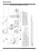
INSTALLATION OPTIONAL FAN INSTALLATION For pedestal unit: To install the fan in an installed stove-access from front through the pedestal by following the directions below. If the stove is not installed - access through rear and follow steps 4 to 17. 2) Remove valve cover plate by removing 2 screws. 3) Remove wire from piezo ignitor. 4) Screw the four 8-32 x3/4 screws provided into the nutserts as shown in diagram 3. Do not tighten screws. 5) Push all the fan wires through the hole on the fan assembly.
INSTALLATION 10) Put the insulation gasket on the back of the fan. Line up the keyhole slots with the matching screws and pull back slightly to lock into place. While holding fan assembly in place, tighten screws. 11) Remove the dummy plug from the right side of the bottom shield or pedestal and install the supplied fan switch. 12) Attach the hot wire from power cord to the thermodisc.
INSTALLATION VENTING INTRODUCTION INSTALLATION PRECAUTIONS VENT RESTRICTOR POSITION The DV Stove Horizontal Vent Kit and the Simpson Dura-Vent Direct Vent System Model DV-GS venting systems, in combination with the Classic Direct Vent Freestanding Gas Stove, C34B-NG/C34G-NG and C34B-LP/C34G-LP, have been tested and listed as direct vent heater systems by Warnock Hersey.
H= *Not to be installed above a meter/regulator assembly within 36" (90 cm) horizontally from the centre-line of the regulator. J= clearance to service regulator vent outlet [*min. 36" (90cm)] K= clearance to non-mechanical air supply inlet to building or the combustion air inlet to any other appliance [*12 inches] L= clearance to a mechanical air supply inlet [*min. 72" (1.8 m) M= **clearance above paved side-walk or a paved driveway located on public property [*84" (2.1 m) min.
INSTALLATION RIGID PIPE VENTING COMPONENTS LIST All Simpson Dura-Vent components are available directly from FPI.
INSTALLATION RIGID PIPE VENTING SYSTEMS Horizontal or Vertical Terminations Alternate Horizontal Termination Caps WARNING: Do not combine venting components from different venting systems. However use of the the AstroCapTM and FPI Riser is acceptable with all systems. This product has been evaluated by Intertek for using a Dura-Vent Flue Adaptor in conjunction with Selkirk Direct-Temp and Ameri Vent Direct venting systems.
INSTALLATION VENTING ARRANGEMENTS HORIZONTAL TERMINATIONS FOR ALL VENTING SYSTEMS The shaded areas in the diagram below show all allowable combinations of vertical runs with horizontal term-inations. Maximum one 90 O elbow (two 45 o elbows equal one 90 o elbow). Propane and Natural Gas: Residential, Manufactured and Mobile Homes Installations The venting arrangements diagrammed below, have a min. of 75% (flue loss) efficiency with Fan Off, as required for manufactured homes.
INSTALLATION Horizontal Venting with Two (2) 90o Elbows One 90o elbow = Two 45o elbows. Option V A) 4' Min. B) 5' Min. C) 6' Min. H + H1 6' Max. 7' Max. 8' Max. With these options, maximum total pipe length is 30 feet with minimum of 6 feet total vertical and maximum 8 feet total horizontal. Please note minimum 1 foot between 90o elbows is required. Lengths do not include elbow indicated. Vent restrictor position C (fully open), refer to page 9.
INSTALLATION DV STOVE HORIZONTAL VENT KIT DV 2 ft. Stove Vent Kit (Part # 946-116) and DV 4 ft. Stove Vent Kit (946-216) include all the parts needed to install the C34 with minimum horizontal and vertical vent dimensions. For installations that require longer vertical and/or horizontal vents use the Dura-Vent system as shown on page 17. Qty. Description 1 Rigid Pipe Section (Kit # 946-116: 2 ft. (1.2m) length, Kit # 946-216: 4 ft. (1.
INSTALLATION e) Cut the 2 ft. or 4 ft. section of rigid pipe to length. Ensure that the pipe length when cut will seat onto both the starter collar and the 90o elbow. Crimped section of rigid pipe seats into the 90 o elbow. Only cut the uncrimped side of pipe. Dismantle all pipe sections including vent terminal. 3) Attach the 4" dia. flex liner to the vent terminal ensuring that the flex overlaps the collar of the vent terminal by a minimum of 1-3/8"(35mm).
INSTALLATION DURA-VENT TERMINATION KIT Planning Your Dura-Vent Installation There are two basic types of Dura-Vent Direct Vent System installations: horizontal termination and vertical termination. Confirm the maximum horizontal run and maximum vertical rise from the diagrams on page 13. DURA-VENT VENTING COMPONENTS The Simpson Dura-Vent Direct Vent System offers a complete line of component parts for installation of both horizontal and vertical installation.
INSTALLATION You will require the following Dura-Vent venting components with your new CLASSIC Direct Vent Freestanding Gas Stove. Please review your product to make sure you have everything you need. In the event that you are missing any part, contact your dealer. Note: These are the minimum components required. Other parts may be required for your particular installation. See page 11 for a venting components list.
INSTALLATION DURA-VENT HORIZONTAL INSTALLATIONS 1) Set the unit in its desired location. Check to determine if wall studs or roof rafters are in the way when the venting system is attached. If this is the case, you may want to adjust the location of the unit. 3) With the pipe attached to the stove, slide the stove into its correct location, and mark the wall for a 10" x 10" (inside dimensions) square hole.
INSTALLATION penetrate the roof. Determine if ceiling joists, roof rafters or other framing will obstruct the venting system. You may wish to relocate the appliance or to offset, as shown in diagram 9 to avoid cutting load bearing members. 4) Attach the Vinyl Siding Standoff (if required) to the Horizontal Vent Termination, but first run a bead of non-hardening mastic around its outside edges, so as to make a seal between vent cap and the standoff.
INSTALLATION tant to support the vent pipe every 3 feet, to avoid excessive stress on the elbows, and possible separation. Wall straps are available for this purpose. See diagram 9. Galvanized pipe and elbows may be utilized in the attic as well as above the roofline. The galvanized finish is desirable above the roofline due to its higher corrosion resistance.
INSTALLATION Support extensions - Round (RDSE) or square (SQSE) The direct vent system must not be connected to a damaged factory-built or masonry chimney. Steep pitched cathedral ceilings may require the use of a support extension. This piece fits down inside the support and can be adjusted to increase the support's length by up to 22". The extension is attached to the support using the eight metal screws provided. Be sure there is at lease a 2 inch overlap where the extension joins the support.
INSTALLATION 7) The connection between the appliance and the Retro Connector may be completed with sections of black direct vent pipe, together with an adjustable length. Flashing is larger than the top of the chimney, then cut and fold flashing as needed to fit chimney. Diagram 7. and the mounting holes line up with the masonry wall. Converting a Masonry Chimney Important: The existing masonry flue opening needs to have an area of at least a 36 sq. in. to insure proper intake/exhaust flow.
INSTALLATION SYSTEM DATA (For 0 to 4,500 feet altitude) Orifice Sizes: Burner Burner Natural Gas Propane #36 #52 This unit is approved in Canada for altitude 0 to 4500 ft. (CAN1 2.17-M90) with the orifice supplied. GAS PIPE PRESSURE TESTING Max. Input Rating Natural Gas 32,000 Btu/h Propane 32,000 Btu/h Min. Input Rating Natural Gas 16,000 Btu/h Propane 16,000 Btu/h Supply Pressure Natural Gas min. max. Propane min. max. HIGH ELEVATION 5.0" w.c 8.0" w.c. 12.0" w.c. 13.0" w.c.
INSTALLATION LOG INSTALLATION push the log down onto the pins. See diagram 3. WARNING: Dangerous operating conditions may occur if these logs are not positioned in their approved locations. Read the instructions below carefully and refer to the diagrams. If logs are broken do not use the unit until they are replaced. Broken logs can interfere with the pilot and burner operation.
INSTALLATION DOOR HANDLE Attach spring handle by rotating counter clockwise onto rod. Ensure that the spring fits into the entire length of the rod. CAUTION Do not wire millivolt remote control wires to the 120V AC wires 3) Install 3 AAA alkaline batteries in transmitter and 4 AA alkaline batteries in the receiver. Install the receiver and its cover in the wall. Switch the remote receiver to "remote" mode. The remote control is now ready for operation.
INSTALLATION WIRING DIAGRAM WARNING: Electrical Grounding Instructions This appliance is equipped with a three pronged (grounding) plug for your protection against shock hazard and should be plugged directly into a properly grounded three-prong receptacle. Do not cut or remove the grounding prong from this plug. This heater does not require a 120V A.C. supply for operation. In case of a power failure, the burner switch and the optional remote control/ thermostat will continue to operate.
OPERATING INSTRUCTIONS OPERATING INSTRUCTIONS 1) Read and understand these instructions before operating this appliance. 2) Check to see that all wiring is correct and enclosed to prevent possible shock. 3) Check to ensure there are no gas leaks. 4) Make sure the glass in the door frame is properly positioned. Never operate the appliance with the glass removed. 5) Verify that the venting is unobstructed. 6) Verify log placement.
OPERATING INSTRUCTIONS COPY OF THE LIGHTING PLATE INSTRUCTIONS AERATION ADJUSTMENT This adjustment is performed by the installer and is primarily used in installations at high elevations. Push in for a yellow flame, or pull out for a bluer flame. The burner aeration is factory set but may need adjusting due to either the local gas supply or altitude. Caution: Carbon will be produced if air shutter is closed too much. Natural Gas -5/16" (7.9 mm) Propane - 5/8" (15.
MAINTENANCE NORMAL OPERATING SOUNDS OF GAS APPLIANCES It is possible that you will hear some sounds from your gas appliance. This is perfectly normal due to the fact that there are various gauges and types of steel used within your appliance. Listed below are some examples. All are normal operating sounds and should not be considered as defects in your appliance. Blower: Regency gas appliances use high tech blowers to push heated air farther into the room.
MAINTENANCE GOLD-PLATED DOORS To remove valve from valve assembly, continue. The 24 carat gold plated finish on the door requires little maintenance, and need only be cleaned with a damp cloth. DO NOT use abrasive materials or chemical cleaners, as they may harm the finish and void the warranty. Clean any fingerprints off before turning the unit on. 11) Remove two (2) thermopile wires. 12) Remove thermocouple with a 9 mm (metric) wrench. 13) Remove pilot nut with an 11 mm wrench.
PARTS LIST MAIN ASSEMBLY Part # Description 3) 4) 5) 6) 7) 490-550 490-552 846-302 936-240 * 490-028 948-074/15 Door Assembly-Gold (no glass) Door Assembly-Black (no glass) Small Glass Glass Gasket (1/8") Nut - 3/8 N/C Jam Glass Frame Door Handle 12) 13) 14) 17) 19) 936-233 846-918 * 471-031 948-101 Door Gasket Hinge Cap (set of 2) Screw 10-24 x 3/4" Door Retainer Clip Spring Handle (Large) 20) 21) 22) 490-917 910-157/P 910-142 910-794 Complete Fan Assembly (Optional) Blower Motor (120V) Fan Auto
PARTS LIST BURNER ASSEMBLY & LOG SET Part # 910-190 * * Description Piezo Ignitor & Nut Control Panel Control Panel Decal 68) 69) 492-562/P 492-563/P 910-378 910-380 910-034 910-035 904-604 904-390 936-170 936-175 948-280 Valve Assembly - S.I.T. - Nat. Gas Valve Assembly - S.I.T. - Propane Valve - S.I.T. - Nat. Gas Valve - S.I.T. - Propane Pilot Assy 3 Flame-S.I.T. -NG Pilot Assy 3 Flame-S.I.T.
PARTS LIST BASE OPTIONS Part # 100) 102) 103) 108) 109) 110) 121) 490-921 948-216 904-257 * 910-246 910-140 910-327 490-005 140) 850-127 850-126 850-128 142) 850-125 34 Description Complete Floor Shield Regency Logo Magnetic Catch (Large) 11" Pedestal Hinge Burner ON/OFF Switch Fan HIGH/OFF/LOW Switch Strain Relief for Power Cord Access Panel Cast Legs - Gold (4/set) Cast Legs - Black (4/set) Cast Legs - Brush Nickel (4/set) Steel Legs (4/set) 100) 102) 103) 108) 109) 110) 123) 124) 125) Part # Descr
WARRANTY Regency Fireplace Products are designed with reliability and simplicity in mind. In addition, our internal Quality Assurance Team carefully inspects each unit thoroughly before it leaves our facility. FPI Fireplace Products International Ltd. is pleased to extend this limited lifetime warranty to the original purchaser of a Regency Product. This warranty is not transferable.
Regency fireplace products are designed with reliability and simplicity in mind. In addition, our internal Quality Assurance Team carefully inspects each unit thoroughly before it leaves our door. Fireplace Products International Ltd. is pleased to extend this Limited Lifetime Warranty to the original purchaser of a Regency Product. See the inside back cover for details. Register your Regency online at http://www.regency-fire.