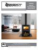
CS2400 Alterra® Freestanding Wood Stove Owner's & Installation Manual Tested by: Installer: Please complete the details on the back cover and leave this manual with the homeowner. Homeowner: Please keep these instructions for future reference. 918-926a FPI FIREPLACE PRODUCTS INTERNATIONAL LTD. 6988 Venture St.
Thank-you for purchasing a REGENCY FIREPLACE PRODUCT. The pride of workmanship that goes into each of our products will give you years of trouble-free enjoyment. Should you have any questions about your product that are not covered in this manual, please contact the REGENCY DEALER in your area. Keep those REGENCY FIRES burning. SAFETY NOTES: If this wood stove is not properly installed, a house fire may result.
SAFETY LABEL This is a copy of the label for reference only, that accompanies each CS2400 Wood Stove. We have included a copy of the contents here for your review. NOTE: Regency units are constantly being improved. Check the label on the unit and if there is a difference, the label on the unit is the correct one.
TABLE OF CONTENTS SAFETY LABEL MAINTENANCE DIMENSIONS Maintenance ................................................................27 Door catch Adjustment ................................................27 Door Gasket ................................................................27 Glass Maintenance ......................................................27 Glass Replacement .....................................................27 Unit Dimensions ..........................................................
DIMENSIONS UNIT DIMENSIONS 26-3/8” 27-5/16” to rear shield 26-5/16” 23-3/8” 28-7/8” to optional fan 21-1/2” 8-5/16” 6" flue collar 17-1/8” CL for outside air 41-1/8” 39-1/8” 44-7/8” Shown with optional fan installed.
INSTALLATION 3) To insure vertical alignment, suspend a plumb bob from the ceiling over the exact center of your stove flue and mark a spot on the ceiling to indicate the center of the chimney. INSTALLATION CHECKLIST 1) Locate appliance: a) Refer to "Residential Installation" section.
INSTALLATION MINIMUM CLEARANCE TO COMBUSTIBLE MATERIALS MEASUREMENTS "FROM UNIT" ARE FROM THE SIDE SHIELDS OF THE STOVE TO A SIDE WALL OR TO A CORNER, AND FROM THE REAR HEAT SHIELD TO A BACK WALL B E A F D C F C NOTE: Be aware that local Codes and Regulations may override some clearances listed in this manual. Check with your local inspector. Residential Installation “C” Vent (Single Wall) Unit CS2400 From Unit From Corner From Flue Center-line A B C D E F 18" 12" 6.
INSTALLATION MINIMUM ALCOVE CLEARANCE TO COMBUSTIBLE MATERIALS MEASUREMENTS "FROM UNIT" ARE FROM THE SIDE SHIELDS OF THE STOVE TO A SIDE WALL OR TO A CORNER, AND FROM THE REAR HEAT SHIELD TO A BACK WALL The Regency Freestanding models have been alcove approved and must be installed with a listed double wall connector to the ceiling level. Note: Minimum alcove ceiling height - 84" Maximum depth of alcove - 36" Minimum Alcove Clearance to Combustible Materials Unit From Back Shield + Side Shields.
INSTALLATION STEP BY STEP CHIMNEY AND CONNECTOR INSTALLATION Note: These are a generic set of chimney installation instructions. Always follow the manufacturers own instructions explicitly. Check the Minimum Recommended Flue Heights section (Table 1). 1) With your location already established, cut and frame the roof hole. It is recommended that no ceiling support member be cut for chimney and support box installation. If it is necessary to cut them, the members must be made structurally sound.
INSTALLATION MASONRY CHIMNEY Ensure that a masonry chimney meets the minimum standards of the National Fire Protection Association (NFPA) by having it inspected by a professional. Make sure there are no cracks, loose mortar or other signs of deterioration and blockage. Have the chimney cleaned before the stove is installed and operated. When connecting the stove through a combustible wall to a masonry chimney, special methods are needed.
INSTALLATION COMBUSTIBLE WALL CHIMNEY CONNECTOR PASS-THROUGHS Minimum chimney clearance to brick and combustibles 2 in. (50.8mm) Method A: 12" (304.8 mm) Clearance to Combustible Wall Member: Chimney Flue Using a minimum thickness 3.5" (89 mm) brick and a 5/8" (15.9 mm) minimum wall thickness clay liner, construct a wall pass-through. The clay liner must conform to ASTM C315 (Standard Specification for Clay Fire Linings) or its equivalent. Keep a minimum of 12" (304.
INSTALLATION TABLE 1 MINIMUM RECOMMENDED FLUE HEIGHTS IN FEET (Measured from the top of the unit) # OF ELBOWS ELEVATION (FT) ABOVE SEA LEVEL 0 2 x 15o 4 x 15o 2 x 30o 4 x 30o 2 x 45o 4 x 45o 0-1000 12.0 13.0 14.0 15.0 18.0 16.0 20.0 1000-2000 12.5 13.5 14.5 15.5 19.0 16.5 21.0 2000-3000 13.0 14.0 15.0 16.0 19.5 17.0 21.5 3000-4000 13.5 14.5 15.5 17.0 20.0 18.0 22.5 4000-5000 14.0 15.0 16.0 17.5 21.0 18.5 23.0 5000-6000 14.5 15.5 17.0 18.0 21.5 19.0 24.
INSTALLATION MOBILE HOME INSTALLATION Once you have properly marked the position of your unit and the floor protection as outlined in the Residential Installation items #1 through #8, a supply of fresh air has to be supplied to your unit. Cut a minimum 4 inch diameter hole through your outside wall. Use 4" duct pipe with a mesh grill to pipe fresh air into the back shield area.
INSTALLATION LISTED COMPONENTS FOR MOBILE HOME INSTALLATION The Regency CS2400 is approved for installation in a Mobile Home if one of the following pipe systems is used. A chimney complying with the requirements for type HT chimney, factory built, Residential type and Building Heating appliance, (UL103, ULCS629, OR2) code- approved masonry chimney with a flue liner U.S.
INSTALLATION STAINLESS STEEL SMOKE DEFLECTOR ADJUSTMENT / REPLACEMENT The stainless smoke deflector is located in the upper front area of the firebox. The deflector is held in place with 2 bolts Prior to the first fire, ensure deflector is seated properly and secured with 2 hand tightened bolts. Smoke deflector installed with 2 bolts. Smoke deflector Note: This is a view from the back of the unit through the top.
INSTALLATION FLUE BAFFLE & SECONDARY AIR TUBE INSTALLATION The flue baffle system located in the upper area of the firebox is removable to make cleaning your chimney system easier. The baffles must be installed prior to your first fire. Smoke spillage and draft problems may occur if the baffles are improperly positioned. Check the position of the baffles on a regular basis as they can be dislodged if too much fuel is forced into the firebox.
INSTALLATION SIDE PANEL INSTALLATION One set of side panels needs to be installed on the stove. When installing stainless steel side panels - follow the handling and cleaning instructions below. Before installation, panels must be handled and cleaned as per instructions noted below: Stainless Steel Panels • Stainless panels must be inspected for scratches and dimples prior to installation. All claims to be recorded at this time. Claims for damage after installation will not receive consideration.
INSTALLATION ASH DRAWER OPTION 1) Open the main top door and the center door on the front of the unit. 4) Push the ash plug into the hole inside the firebox and replace all the bricks except for the brick over the ash plug. See brick diagrams in manual. 5) Position ash drawer lid in 'Open' position on the ash drawer lid (towards the front) as shown below. 2) Remove the bricks from the floor of the firebox. Ash drawer lid 6) Slide in ash drawer.
INSTALLATION LOWER SURROUND DOOR REVERSAL (LEFT TO RIGHT SIDE OPENING) 1) The surround door can be reversed - to open to the left. Make sure stove has cooled, open the door - and remove it from the hinge by removing 2 bolts. 6) Reinstall the door (do not rotate) onto the hinge on the left side with the 2 bolts removed in Step 1. 2) Remove and discard the latch on the left side of the unit by removing 2 bolts. 3) Replace with the latch contained within the manual package.
INSTALLATION CAST DOOR REVERSAL (LEFT TO RIGHT SIDE OPENING) 1) The door can be reversed - so that it will open to the left. Make sure stove has cooled to room temperature. Open the door to about 45°- then remove it from the hinge by lifting up and out. Note: Door is heavy. 6) Remove the glass from the door and flip it around 180° - so the painted strip is at the bottom of the door. 7) Flip the handle around 180° and reattach to the door with 2 botls.
INSTALLATION WOOD STORAGE 3) Manoeuvre ashlip into position on an angle - the tabs on the ashlip rest behind side walls on unit - see diagrams below. When storing wood within pedestal- ensure wood does not protrude past door opening. Do not store newspaper within pedestal. Note: Please refer to local codes. (B365, NFPA 211) and your local jurisdiction.. Tabs on ashlip Store wood behind opening ASHLIP INSTALLATION 1) Open lower surround door.
INSTALLATION OPTIONAL OUTDOOR AIR KIT INSTALLATION 1) Remove 4 screws from locations shown below to remove backing plate. 2) Center the plate / pipe over the opening on the back of the stove. Secure with 4 self tapping screws. 3) Reinstall the backing plate over the air kit pipe. Secure with 4 screws removed from step 1. 4) Slide cap over end to pipe to complete the installation.
INSTALLATION BLOWER/FAN INSTALLATION 1) Remove the five screws from the back panel of the unit - to remove the fan cover plate. 2) Slide the fan up into the rear heat shield. 3) After aligning holes, secure the fan to the rear heat shield using the five screws removed earlier. 4) Secure the bottom of the fan using the two fan clips (in manual package) and two bottom screws removed in step 1. Note: The connection cord should not be in contact with any hot surfaces.
OPERATING INSTRUCTIONS OPERATING INSTRUCTIONS 8) Do not place anything on the stove top during the curing process. This may result in damage to your paint finish. With your unit now correctly installed and safety inspected by your local authority, you are now ready to start a fire. Before establishing your first fire, it is important that you fully understand the operation of your draft control. 9) During the first few days it may be more difficult to start the fire.
OPERATING INSTRUCTIONS INSTALLATION ASH DISPOSAL During constant use, ashes should be removed every few days. The Ash Drawer option features a convenient ash dump for easy removal of ash, refer to the "Modular Options" section. 3) Open the lower surround door by hooking two fingers in the slot near the left side - pull open towards the right. Safety Precautions 1) Do not allow ashes to build up to the loading doors! Only remove ashes when the fire has died down. Even then, expect to find a few hot embers.
MAINTENANCE SAFETY GUIDELINES AND WARNINGS 1) Never use gasoline, gasoline type lantern fuels, kerosene, charcoal lighter fuel, or similar liquids to start or ‘freshen up’ a fire in your heater. Keep all such liquids well away from the heater while it is in use. 2) Keep the door closed during operation and maintain all seals in good condition. 3) Do not burn any quantities of paper, garbage, and never burn flammable fluids such as gasoline, naptha or engine oil in your stove. Some fuels (eg.
MAINTENANCE MAINTENANCE It is very important to carefully maintain your fireplace stove, including burning seasoned wood and maintaining a clean stove and chimney system. Have the chimney cleaned before the burning season and as necessary during the season, as creosote deposits may build up rapidly. Moving parts of your stove require no lubrication. CREOSOTE DOOR CATCH ADJUSTMENT The door catch may require adjustment as the door gasket material compresses after a few fires.
MAINTENANCE Annual Maintenance Completely clean out entire unit Annually Inspect air tubes, baffles and bricks Replace any damaged parts. Adjust door catch / latch If unable to obtain a tight seal on the door - replace door gasket seal. Readjust latch after new gasket installed. Inspect condition and seal of: Glass Gasket Door Gasket Paper Test 28 Perform paper test - replace gasket if required Test the seal on the loading door with a paper bill.
PARTS LIST MAIN ASSEMBLY 1) 2) 3) 4) 5) 6) 7) 8) 9) 10) 11) 12) 13) 14) 15) 16) 17) 18) 19) 20) 21) Part # Description 156-261 156-524 146-211 156-261 076-011 076-011 200-917 146-003 146-002 146-514 156-523 220-516 156-523 146-517 146-517 146-512 146-011 146-008 948-216 076-022 820-482 Cast Door Surround Door Cast Top Surround Top/ Bottom Front Leg Rear Fan Clip Fan Assembly Side Shield (LH) Side Shield (RH) Pedestal Assembly Door Hinge Assembly Ash Drawer Assembly Door Catch Assembly Heat Shield Assemb
PARTS LIST FAN ASSEMBLY 1) 2) 3) 4) 5) 6) 7) 8) Part # Description 076-201 222-022 222-036 200-227 200-228 200-229 910-157/P 910-142 Fan Housing Front Fan Housing Bottom Sensor Mount Fan Bracket Right Hand Fan Bracket Left Hand Fan Housing Back Fan Thermodisc 7 JAKEL INC. J250-150-O44003 115V. 60HZ. 1.1A T.P.L B T.P.
WARRANTY Regency Fireplace Products are designed with reliability and simplicity in mind. In addition, our internal Quality Assurance Team carefully inspects each unit thoroughly before it leaves our door. FPI Fireplace Products International Ltd. is pleased to extend this limited lifetime warranty to the original purchaser of a Regency Product. This warranty is not transferable.
Register your Regency® warranty online www.regency-fire.com Reasons to register your product online today! • View and modify a list of all your registered products. • Request automatic email notification of new product updates. • Stay informed about the current promotions, events, and special offers on related products.