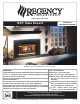
www.regency-fire.com E21 Gas Insert Owners & Installation Manual MODELS: E21-NG1 Natural Gas E21-LP1 Propane WARNING: FOR YOUR SAFETY If the information in these instructions are not followed exactly, What to do if you smell gas: a fire or explosion may result causing property damage, Do not try to light any appliance personal injury or loss of life. Do not touch any electrical switch: do not use any phone in your FOR YOUR SAFETY building.
CONGRATULATIONS! You are the owner of a state-of-the-art Gas Insert by: FPI FIREPLACE PRODUCTS INTERNATIONAL LTD. The Regency Gas Fireplace Series has been designed to provide you with all the warmth and charm of a fireplace, at the flick of a switch. The models E21-NG1 and E21-LP1 of this series have been approved by Warnock Hersey for safety. As it also bears our own mark, it promises to provide you with economy, comfort and security for many trouble free years to follow.
TABLE OF CONTENTS E21 GAS INSERT Page Page SAFETY LABEL OPERATING INSTRUCTIONS Safety Label ..................................................................4 Operating Instructions .................................................20 Lighting Procedure ......................................................20 Shutdown Procedure ...................................................20 First Fire ......................................................................20 Copy of Lighting Plate Instructions ...
For the State of Massachusetts, installation and repair must be done by a plumber or gasfitter licensed in the Commonwealth of Massachusetts. For the State of Massachusetts, flexible connectors shall not exceed 36 inches in length. 4 Model/ E21-NG1 Modele: NOT FOR USE WITH SOLID FUEL. NE PAS UTILISER AVEC DU COMBUSTIBLE SOLIDE. Minimum input Maximum input Orifice size Altitude Manifold pressure low Manifold pressure high MADE IN CANADA / FABRIQUE AU CANADA FPI Fireplace Products International Ltd.
INSTALLATION IMPORTANT: SAVE THESE INSTRUCTIONS The Regency Gas Fireplace must be installed in accordance with these instructions. Carefully read all the instructions in this manual first. Consult the "authority having jurisdiction" to determine the need for a permit prior to starting the installation. It is the responsibility of the installer to ensure this fireplace is installed in compliance with the manufacturer's instructions and all applicable codes.
INSTALLATION POLICY FOR SOLID FUEL BURNING & FACTORY BUILT FIREPLACES The Regency E21 may be installed and vented into any solid fuel fireplace that has been installed in accordance with the National, Provincial and local building codes and is constructed of noncombustible materials. 1) Installer must mechanically attach the supplied label to the inside of the firebox of the fireplace into which the gas fireplace insert is installed.
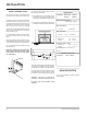
INSTALLATION CLEARANCES TO COMBUSTIBLES The minimum clearance from the side of the appliance to a combustible side wall is 9 inches (229mm). The minimum clearance from the top of the louver to a combustible mantel is 14 inches (356mm). (356mm) The minimum height from the top of the louver to the ceiling is 36 inches (914mm). (914mm) See diagram.
INSTALLATION GAS CONNECTION Only persons licensed to work with gas piping may make the necessary gas connections to this appliance. The gas connection is a 3/8" NPT accessible on the left side of the unit. The gas line connection may be made of rigid pipe, copper pipe or an approved flex connector. (If you are using rigid pipe, ensure that the valve can be removed for servicing.
INSTALLATION WIRING DIAGRAM FOR THE E21-NG1 AND E21-LP1 codes the current CSA C22.1 (in Canada) or with the National Electrical Code ANSI/NFPA 70-1987 (in USA). When connected with 120 volts, the appliance must be electrically grounded in accordance with local codes or, in the absence of local NOTE: This unit is equipped with a heat sensor thermodisc which will prevent the blower from operating until the unit reaches the correct temperature.
INSTALLATION OFFSET FLUE ADAPTOR A Offset Flue Adaptor Kit, Part #532-920 is available as an accessory to move the flue outlet back for easier liner installations in deep fireplaces. B-Vent chimneys require a 1" clearance to combustibles. A 3" diameter type B-Vent or approved aluminium flex liner may also be used with a 4" to 3" reducing adapter. Consult venting charts and local code requirements. The Regency Insert incorporates its own internal draft hood, so no additional external draft hood is required.
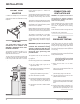
INSTALLATION Valve Description 1) Gas cock knob 2) Manual high/low adjustment 3) Pilot Adjustment 4) Thermocouple Connection 5) Main Operator 6) Outlet Pressure Tap (Manifold Pressure) 7) Inlet Pressure Tap (Supply Pressure) 8) Pilot Outlet 9) Main Gas Outlet 10) Flange Securing Screw Holes 11) Alternative TC Connection Point 12) Thermoelectric Unit 13) Additional Valve Mounting Hole GAS INSERT AERATION SYSTEM The aeration adjustment rod is attached to the air shutter which is located just above the orifice
INSTALLATION LOG SET INSTALLATION 4) Place the Front Left Log B) 02-67 on the 2 front pins. Read the instructions below carefully and refer to the diagrams. If logs are broken do not use the unit until they are replaced. Broken logs can interfere with the pilot operation.
INSTALLATION 7) Tuck the wires into the faceplate to keep them away from the insert using the clip provided. Attach the clip to the rear of the faceplate to ensure that the wires do not touch the side of the unit. See diagram 3. FLUSH GLASS 1) Install the bottom glass trim onto the glass support. 2) Slide the glass into the bottom glass trim and secure with the glass clips using the 2 phillips head screws at the top. 3) Slide the top glass trim by sliding under the two spring clips.
INSTALLATION FLUSH LOUVERS 1) The Top Louver is held in place by Spring Clips. Push into place as shown. OPTIONAL BAY FRONT BAY LOUVERS IMPORTANT Flush glass must stay in place when bay option is used. The bay front is a decorative overlay only. 1) Install top louver by sliding the two bracket clips into the brackets located on top of the bay door. See below. The fitted louver leaves a small gap between faceplate bottom and louver top. 1) Place the bay door onto the 2 pins on the top of the unit.
INSTALLATION Conversion Kit from Natural Gas to Propane Model #533-969 THIS CONVERSION MUST BE DONE BY A QUALIFIED GAS FITTER IF IN DOUBT DO NOT DO THIS CONVERSION !! 1) Turn the unit off and allow it to cool to room temperature. 2) Shut off gass supply 3) Unplug or disconnect power source to stove. 8) Pull off the pilot cap to expose the pilot orifice. 9) Unscrew the pilot orifice with the allen key (provided) and replace with the LP pilot orifice in the kit. 4) Remove glass front (see manual).
INSTALLATION 11) Remove and discard the 3 pressure regulator mounting screws (A), pressure regulator tower (B) and diaphragm (C). 12) Insure that the rubber gasket (D) is properly positioned and install the new HI/LO pressure regulator assembly to the valve using the new screws (E) supplied with the kit. Tighten screws securely. 16) Attach clear label "This unit has been converted to Propane" near or on the serial # decal.
INSTALLATION FULL SCREEN FRONT 1) Hold the full screen door up against the unit in order to make the following wire connections. 3) Completely secure full screen door to the unit by securing 4 screws to the Left and Right Side Trim. Pull the ON/OFF connector wires thru the box and connect them to the switch. Connect the fan switch wires with the wire connectors from the fan speed control. Place clips over wires and tuck into side trim.
INSTALLATION 5) Install Spring Hinges to the Left and Right Side of the bottom of the firebox using 2 screws per hinge. 7) Install the Left and Right Side Screen Doors by placing over top of the hinges on the faceplate. Hold the door at a 45 degree angle to avoid scratching the faceplate. Hinge 6) Place Bottom Frame near hinge. Flip hinge over Bottom Frame and secure with 3 screws each. Hinge Location Screen Door Bottom Frame 8) Close screen doors.
INSTALLATION Option 1: REMOTE CONTROL Option 2: WALL SWITCH Option 3: WALL THERMOSTAT Use the Regency Remote Control Kit approved for this unit. Use of other systems may void your warranty. 1) Run the wire through the right or left side inlet opening. Be careful not to damage the wire. The remote control kit comes with a hand held transmitter, a receiver and a wall mounting plate. Note: We recommend a maximum of 15' of wire but if you wish to go with a longer run, use the Thermostat Wire Table.
OPERATING INSTRUCTIONS FINAL CHECK Before leaving this unit with the customer, the installer must ensure that the appliance is firing correctly. This includes: 1) Clocking the appliance to ensure the correct firing rate (rate noted on label) at 15 minutes. 2) If required, adjusting the primary air to ensure that the flame does not carbon. First allow the unit to burn for 15 min. to stabilize. 6) Verify log placement.
OPERATING INSTRUCTIONS COPY OF LIGHTING PLATE INSTRUCTIONS FOR YOUR SAFETY READ BEFORE LIGHTING This appliance must be installed in accordance with local codes, if any; if none, follow the National Fuel Gas Code, ANSI Z223.1/NFPA 54, or Natural Gas and Propane Installations Codes, CSA B149.1. Australia: AG601, New Zealand: NZS 5261 WARNING: If you do not follow these instructions exactly, a fire or explosion may result causing property damage, personal injury or loss of life.
MAINTENANCE AUTOMATIC CONVECTION FAN OPERATION The fan operates automatically, turn the knob on the side of the faceplate to adjust to the desired speed. The fan will turn on as the stove comes up to operating temperature. After the unit has been turned off and the unit cooled to below a useful heat output range the fan will shut off automatically. NORMAL OPERATING SOUNDS OF GAS APPLIANCES It is possible that you will hear some sounds from your gas appliance.
MAINTENANCE DOOR GLASS REPLACEMENT Your Regency stove is supplied with high temperature, 5 mm Neoceram ceramic glass that will withstand the highest heat that your unit will produce. In the event that you break your glass by impact, purchase your replacement from an authorized Regency dealer only, and follow our step-by-step instructions for replacement. Bay Glass Removal 1) Remove the door from the unit and place on a soft surface to prevent scratching.
PARTS LIST MAIN ASSEMBLY Part # Description 530-518/P Fan Assembly 8) 10) 12) 13) 17) 910-331/P 910-750 910-752 * 936-238 936-233 W241050 910-233 * 532-516 910-343 * 532-012 Fan Motor (120V) Power Cord (120V) Wire Harness (Intermediate) Firebox Bottom Soft Fiber Gasket 8mm 3/4" Rope Gasket Fan AUTO ON/OFF Thermodisc - NG Fan AUTO ON/OFF Thermodisc - LP Thermodisc Bracket Draft Hood Slide Plate Spill Switch Spill Switch Bracket Baffle 21) 23) 532-910 532-912 532-914 * * Flush Louver (set)-Black Flush
PARTS LIST BURNER ASSEMBLY & LOG SET Part # Description 533-574/P 533-576/P 910-098 910-099 Valve Assembly- Nat. Gas Valve Assembly - Propane Valve SIT - Nat.
PARTS LIST BAY & FLUSH FRONT ASSEMBLY Part # Bay Door 530-950 106) 940-312/P 107) 936-243 108) 940-313/P 110) 902-183 402-905 402-906 Complete Bay Front c/w Black Trim Side Glass Gasket - Adhesive Backed 7/8" Center Glass Bay Brick Panel - Standard Bay Brick Panel - Standard Brown Bay BricK Panel - Standard Red 111) 112) 113) 400-153 904-196 400-152 Bay Glass Trim Top-Black 1" Round Ceramic Magnet Bay Glass Trim Bottom - Black 402-956 402-958 Gold Trim Bay Front Steel Trim Bay Front * * Glass Retain
PARTS LIST FACEPLATE ASSEMBLY Part # 91) 92) 93) Description 910-330 904-569 910-246 Fan Speed Control (120 V) Fan Speed Control Knob Burner Switch ON/OFF (2 way) 400-950 320-940 400-926 320-942 400-928 320-944 400-959 320-946 Hearth Trim 1" Standard Hearth Trim 1" Oversize Hearth Trim 2" Standard Hearth Trim 2" Oversize Hearth Trim 4" Standard Hearth Trim 4" Oversize Hearth Trim 6" Standard Hearth Trim 6" Oversize 532-918 * * * * * * 532-950 Faceplate & Trim (Set) - Standard-Contour - Black Faceplat
NOTES ___________________________________________________ ___________________________________________________ ___________________________________________________ ___________________________________________________ ___________________________________________________ ___________________________________________________ ___________________________________________________ ___________________________________________________ ___________________________________________________ ______________________________________
NOTES ___________________________________________________ ___________________________________________________ ___________________________________________________ ___________________________________________________ ___________________________________________________ ___________________________________________________ ___________________________________________________ ___________________________________________________ ___________________________________________________ ______________________________________
NOTES ___________________________________________________ ___________________________________________________ ___________________________________________________ ___________________________________________________ ___________________________________________________ ___________________________________________________ ___________________________________________________ ___________________________________________________ ___________________________________________________ ______________________________________
WARRANTY Regency Fireplace Products are designed with reliability and simplicity in mind. In addition, our internal Quality Assurance Team carefully inspects each unit thoroughly before it leaves our facility. FPI Fireplace Products International Ltd. is pleased to extend this limited lifetime warranty to the original purchaser of a Regency Product. This warranty is not transferable.
Regency fireplace products are designed with reliability and simplicity in mind. In addition, our internal Quality Assurance Team carefully inspects each unit thoroughly before it leaves our door. Fireplace Products International Ltd. is pleased to extend this Limited Lifetime Warranty to the original purchaser of a Regency Product. See the inside back cover for details. Register your Regency online at http://www.regency-fire.