U32E Gas Insert Owners & Installation Manual www.regency-fire.com MODELS: U32E-NG5 Natural Gas U32E-LP5 Propane WARNING: FOR YOUR SAFETY Improper installation, adjustment, alteration, service or What to do if you smell gas: maintenance can cause injury or property damage. Refer to Do not try to light any appliance this manual. For assistance or additional information consult Do not touch any electrical switch: an authorized installer, service agency or the gas supplier.
TO THE NEW OWNER Congratulations! You are the owner of a state-of-the-art Gas Insert by FPI. The FPI Gas Insert Series of hand crafted appliances has been designed to provide you with all the warmth and charm of a fireplace, at the flick of a switch. The models U32E-NG5 and U32E-LP5 of this series have been approved by Warnock Hersey for both safety and efficiency. As it also bears our own mark, it promises to provide you with economy, comfort and security for many trouble free years to follow.
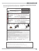
DIMENSIONS 40-1/4" 1-3/8" 20" 21-1/16" 26-1/4" 10-3/4" 13-3/4" 28" Note: Oversize faceplate is 44" x 28" 40-3/4” (1036mm) 7/8” (22mm) 35-15/16” (912mm) 14-5/8” (371mm) 21-15/32” (545mm) 27-7/8” (708mm) 23-15/16” (607mm) 9-15/16” (252mm) Low Profile Faceplate Dimensions INFORMATION FOR MOBILE/MANUFACTURED HOMES AFTER FIRST SALE This FPI product has been tested and listed by Warnock Hersey as a Direct Vent Wall Furnace to the following standards: CAN/ CGA-2.17-M91, and ANSI Z21.88-2009/CSA 2.
TABLE OF CONTENTS REQUIREMENTS MA Code - CO Detector.................................................6 (for the State of Massachusetts only) ............................6 INSTALLATION Important Message ......................................................8 For Your Safety ..............................................................8 Specifications ................................................................8 Gas Pressure Testing ....................................................
SAFETY LABEL This is a copy of the labels that accompany each U32E-5 Gas Insert. We have printed a copy of the contents here for your review. The safety label is located on a plate inside the base of the unit visible when the bottom louver is opened. NOTE: FPI units are constantly being improved. Check the label on the unit and if there is a difference, the label on the unit is the correct one.
REQUIREMENTS MA Code - CO Detector (for the State of Massachusetts only) 5.08: Modifications to NFPA-54, Chapter 10 (2) Revise 10.8.
INSTALLATION IMPORTANT MESSAGE SAVE THESE INSTRUCTIONS The U32E-5 Gas Insert must be installed in accordance with these instructions. Carefully read all the instructions in this manual first. Consult the "authority having jurisdiction" to determine the need for a permit prior to starting the installation. It is the responsibility of the installer to ensure this fireplace is installed in compliance with manufacturers instructions and all applicable codes.
INSTALLATION IMPORTANT MESSAGE SAVE THESE INSTRUCTIONS The FPI Gas Insert must be installed in accordance with these instructions. Carefully read all the instructions in this manual first. Consult the building authority having jurisdiction to determine the need for a permit prior to starting the installation. NOTE: Failure to follow the instructions could cause a malfunction of the heater which could result in death, serious bodily injury, and/ or property damage.
INSTALLATION INSTALLATION CHECKLIST Before installing vent system ensure that the damper plate is open and secure to prevent the damper plate from falling down and crushing the liner. The FPI Gas Insert is installed as listed. 1) Check all clearances to combustibles, (Refer to sections "Minimum Fireplace Dimensions and Clearances to Combustibles) 2) Make the gas connection. (Refer to section "Gas Connection") 3) Install the 3" flue liner to the sliding connector plate.
INSTALLATION VENTING The Air Intake pipe must be attached to the inlet air collar of the termination cap. THE APPLIANCE MUST NOT BE CONNECTED TO A CHIMNEY FLUE SERVING A SEPARATE SOLID FUEL BURNING APPLIANCE. This appliance is designed to be attached to two 3" (76mm) co-linear aluminium flex running the full length of the chimney. The flue length must be a minimum length of 8 ' (2.44m) and a maximum of 35' (10.7m). See chart below for minimum distances from roof.
INSTALLATION 1) Make sure the valve is in the "OFF" position. 2) Loosen the "IN" and/or "OUT" pressure tap(s), turning counterclockwise with a 1/8" wide flat screwdriver. 3) Attach manometer to "IN" and/or "OUT" pressure tap(s) using a 5/16" ID hose. 4) Light the pilot and turn the valve to "ON" position. OPTIONAL BRICK PANEL 1) Unwrap the brick pattern panels from the protective wrapping. 2) Remove the glass front if it is already installed, see "Standard Flush Door" section.
INSTALLATION LOG SET INSTALLATION Read the instructions below carefully and refer to the images. Dangerous operating conditions may occur if the logs are not positioned in their correct locations. If the logs are broken do not use the unit until they are replaced. Broken logs can interfere with the pilot operation. 2) Spread vermiculite around the exposed firebox base. Then take some embers and spread them over the vermiculite as shown.
INSTALLATION 6) Fit the groove in log 27-34 into the tab on the right side of the burner. Rest the other end of log 27-34 on the notch in log 27-33. 27-32 27-34 5) Fit log 27-33 into the pins at the front of the burner. Tab 27-33 27-34 27-33 7) Fit the bottom end of log 27-35 into the pin in log 27-33 and rest the top end of log 27-35 on the notch in log 27-31.
INSTALLATION 9) Place embers along the front of the burner as shown. Ensure not to cover any burner ports. 27-35 8) Fit log 27-36 into the pins on logs 27-33 and 27-31. Embers 10) Separate platinum embers and place on the burner just in front of the logs as shown. Avoid stacking platinum embers.
INSTALLATION Completed Log Set Installation 27-31 27-35 27-33 U32E-5 FPI Direct Vent Gas Insert 27-32 27-34 27-36 15
INSTALLATION REGENCY FACEPLATE & TRIM INSTALLATION 9) Attach the brass trim to the faceplate by drilling a 1/8" hole through into the faceplate using the hole in the trim as a guide. Fasten the trim to the faceplate panels using the plated screws. Diagram 4. 1) Lay the faceplate panels flat, face down on something soft so they don't scratch. 2) Take the top faceplate and align the holes in it with the holes in the side panels.
INSTALLATION STANDARD FLUSH DOOR The standard flush door comes with a black frame. To install the frame, simply hook the top door flange onto the top of the unit and swing the door towards the unit, diagram 1. Be careful that the glass gasket does not roll up; there must be a gap between the gasket and the door lip to ensure that the door sits securely on the unit. Diagram 2. Use the hook to pull the spring out until you can put the hook into the slot on the bottom door bracket. Repeat for 2nd spring.
INSTALLATION CONVERSION FROM NG TO LP For U32E-5 Using SIT 886 NOVA Gas Valve THIS CONVERSION MUST BE DONE BY A QUALIFIED GAS FITTER IF IN DOUBT DO NOT DO THIS CONVERSION !! Each Kit contains one LPG Conversion Kit #514-972 LPG Conversion Kit Contains: Qty. Part # 1 904-390 1 918-590 1 1 1 1 1 908-528 904-529 911-009 910-101 918-861 3b) Remove the Burner Tray by removing the screws on each side of the tray. Push the tray to the left and lift up. 6) Remove burner orifice with a 1/2" wrench.
INSTALLATION FULL SCREEN DOORS 1) Hold the full screen door frame up against the unit in order to make the following wire connections. 3) Completely secure the full screen door frame to the unit by securing 4 screws to the Left and Right Side Trims. Pull the ON/OFF connector wires from the firebox and connect them to the switch. Connect the fan switch wires with the wire connectors from the fan speed control. Place clips over wires and tuck into side trim. .
INSTALLATION 4) Install Spring Hinges on the Left and Right Side of the bottom of the firebox using 2 screws per hinge. 7) Install the Left and Right Side Screen Doors in the fully open position by placing over top of the hinges on the full screen door frame. Hinge 5) Place Bottom Frame near hinge. Flip hinge over Bottom Frame and secure with 3 screws. Screen Door Hinge Location Bottom Frame 8) Close screen doors.
INSTALLATION CONTEMPORARY FACEPLATE AND DOORFRAME INSTALLATION Kit# 425-914 Contents List: 1 1 1 2 2 4 1 1 1) Note: Ensure that the flanges on the sides of the firebox are on the outside, when installing the faceplate (see below).
INSTALLATION 7) Install the door frame by hooking the top flange over the top of the glass door. 8) Lower the door frame gently into place. 9) Run supplied 120V power cord along front face of masonry fireplace and plug into nearest receptacle. 10) Slide unit into final position.
INSTALLATION OPTIONAL HEARTH TRIM INSTALLATION The Hearth Trim is an option that can be used to finish off the installation when the bottom of the fireplace is higher than the hearth or to raise the fireplace. The faceplate is assembled first and then the hearth trim is attached to the faceplate. There are 2 Hearth Trim options; a 2" and a 4".
INSTALLATION LOW PROFILE FACEPLATE INSTALLATION 1) Attach the inner faceplate panel to the insert body using 4 screws in the locations shown below. 4) Tuck the wires into the clip to keep them away from the insert using the clip provided. Attach the clip to the rear of the faceplate to ensure that the wires do not touch the side of the unit. The power cord should be run behind the inner faceplate panel.
INSTALLATION 8) Attach the bottom louver to the 2 hinges using 2 screws per hinge. 10) Take the outer faceplate, line up the openings on the left and righ legs and install onto the inner faceplate panel pins. Diagram 7 9) Install the top door pressure retainer, required.
INSTALLATION LOW PROFILE HEARTH TRIM INSTALLATION Hearth Trim is an option that can be used to finish off the installation when the bottom of the fireplace is higher than the hearth or to raise the fireplace. 1) For units L390E/HZI390E/L540E/HZI540E–remove 4 screws in locations shown below to remove outer faceplate. ** If no screw holes are present. 3) Remove backing plate by removing 4 screws–lay down flat.
INSTALLATION OPTIONAL WALL THERMOSTAT OPTIONAL REMOTE CONTROL A wall thermostat may be installed if desired, follow the wiring diagram below. FPI offers an optional programmable thermostat but any 250-750 millivolt rated non-anticipator type thermostat that is CSA, ULC or UL approved may be used. Use the FPI Remote Control Kit approved for this unit. Use of other systems may void your warranty.
INSTALLATION GT REMOTE INSTALLATION 1) Shut off the gas supply and disconnect all power to the unit. 8) Plug in receiver DC supply wire to the DFC supply- as shown below. 2) Remove the louvers, bay door or faceplate if installed. 3) Disconnect battery pack - located on the floor of the unit, as shown below and discard. Do not use battery pack with receiver. 9) Install 4 - AA batteries into the receiver, ensure correct polarity. 4) Remove DFC (digital firebox control box) from the floor of the unit.
INSTALLATION GTM REMOTE INSTALLATION 1) Shut off the gas supply and disconnect all power to the unit. 2) Remove the louvers, bay door or faceplate, if installed. 3) Disconnect battery pack - located on the floor of the unit, as shown below. Do not use battery pack with receiver. 4) Remove DFC (digital firebox control box) from the floor of the unit. 6) Locate green and white ON/OFF wires. Connect the TPTH and TH wires - green to green and white to white as shown below.
INSTALLATION 10) Install 4 - AA batteries into the receiver. Ensure correct polarity. 13) Reinstall the DFC box onto the velcro pad on the floor of the unit. 14) Install the heat shield to the receiver with two screws and attach to the floor of the unit with a velcro pad. Heat shield 11) Plug receiver wire harness into the back of the receiver and bundle wires with the wire clip - as shown below. 15) Reverse steps 5 and 4. 16) Match the remote control to the receiver - see remote control instructions.
INSTALLATION WIRING DIAGRAMS This heater does not require a 120V A.C. supply for operation. In case of a power failure, the burner switch and the optional remote control/ thermostat will continue to operate. However, a 120V A.C. power supply is needed for the fan/blower operation. Caution: Ensure that the wires do not touch any hot surfaces and are away from sharp edges.
OPERATING INSTRUCTIONS LIGHTING PROCEDURE COPY OF LIGHTING INSTRUCTION PLATE IMPORTANT To ignite or reignite the pilot, you must first remove the glass door. FOR YOUR SAFETY READ BEFORE LIGHTING 1) Press and release on ON/OFF button once on the remote control or ON/OFF switch. 2) After approximately 4 seconds the spark ignition system will spark for 60 seconds to light the main burner. 3) The unit will turn on.
OPERATING INSTRUCTIONS INSTALLATION OPERATING INSTRUCTIONS Before operating this appliance, proceed through the following check list. 1) Read and understand these Instructions before operating this appliance. 2) Check to see that all wiring is correct and enclosed to prevent possible shock. 3) Check to ensure there are no gas leaks. 4) Make sure the glass door is in place. Never operate the appliance with the door glass removed. 5) Verify that all venting and the cap is unobstructed.
OPERATING INSTRUCTIONS NORMAL OPERATING SOUNDS OF GAS APPLIANCES It is possible that you will hear some sounds from your gas appliance. This is perfectly normal due to the fact that there are various gauges and types of steel used within your appliance. Listed below are some examples. All are normal operating sounds and should not be considered as defects in your appliance. Blower: FPI gas appliances use high tech blowers to push heated air farther into the room.
MAINTENANCE PILOT ADJUSTMENT Periodically check the pilot flames. Correct flame pattern has two strong blue flames: 1 flowing around the flame sensor and 1 flowing across the burner (it does not have to be touching the burner). Burner Flame Sensor Pilot Ignitor Note: If you have an incorrect flame pattern, contact your Regency® dealer for further instructions. Incorrect flame pattern will have small, probably yellow flames, not coming into proper contact with the rear burner or flame sensor.
MAINTENANCE Bay Glass Removal TO REMOVE FAN: 1) Remove the door from the unit and place on a soft surface to prevent scratching. 1) Turn the unit off and allow it to cool to room temperature. 2) Remove the nuts holding the glass retainers in place. 2) Unplug or disconnect power source to stove. 3) Remove the glass retainers (sides, top and bottom). 3) Remove glass front (see section "Standard Flush Door.") 4) Replace the glass. The glass must have gasketing around it.
MAINTENANCE VALVE REPLACEMENT 10) Remove the 11 screws securing the valve tray in place - then lift the entire assembly out. 1) Shut off the gas supply. 2) Remove the louvers (and bay door if installed). 3) Open the flush door and remove the door. 4) Remove the logs and brick panels. 5) Remove the grate by loosening the two screws and sliding the grate out. 11) Push the valve assembly to the left and lift the entrire assembly out.
PARTS LIST MAIN ASSEMBLY Part # Description 1) 420-122 2) 420-142 422-518/P 3) 910-215/P 5) 910-750 910-752 7) 910-142 8) * 9) * 10) 420-140 12) 420-119 13) * 14) 948-045 15) 948-247 16) 948-025 17) * 18) * 19) * 514-972 918-846 Fan Access Panel Gasket - Fan Access Panel Fan Assembly: Fan Motor (120 V) Power Cord (120 V) Wire Harness (intermediate) Thermodisc-Fan Auto ON/OFF Fan Switch Cover Thermodisc Bracket Flue Restrictor Air Hood Levelling Bolt 5/16 x 3" Hex Hd Jack Chain Spring Lever Handle Door Ex
PARTS LIST BURNER ASSEMBLY Part # Description 423-574E/P 423-576E/P 52) 911-004 911-005 Valve Assembly - NG Valve Assembly - LP Valve - SIT NG Valve - SIT LP 55) * 58) 904-240 904-390 936-170 66) 911-006 911-007 67) * 68) W840470 Valve Tray Burner Orifice Nat.
PARTS LIST FLUSH FRONT ASSEMBLY Part # 422-530 112) 904-196 135) 940-307/P 137) 904-691 139) 936-155 Description Flush Door Complete Flush Door Assy 1" Round Magnet Flush Glass U Clip Tadpole Glass Gasket 137 139 135 112 137 137 112 149 137 112 FLUSH FRONT 112 40 140 U32E-5 FPI Direct Vent Gas Insert
PARTS LIST FACEPLATE ASSEMBLY Part # 402-919 Description Part # 51) * 59) * 60) * 402-534 65) * 68) * 70) * Complete Faceplate (Set) Contour with Black Trim-Oversize Faceplate Side Right - Oversize Faceplate Top - Oversize Faceplate Side Left Assy-Oversize Trims Pkg.
PARTS LIST CONTEMPORARY FACEPLATE AND DOOR FRAME Part # 1) 2) 3) 4) 425-512 425-513 425-514 425-942 Description Door Bottom Assembly Frame Inside Faceplate Outside Hearth Trim 3 2 1 42 U32E-5 FPI Direct Vent Gas Insert
PARTS LIST LOW PROFILE FACEPLATE Part # 1) 2) 3) 4) 5) * * * * * Description Backplate Assembly Bottom Louver Right mounting bracket Left mounting bracket Front Frame 5 4 1 2 3 U32E-5 FPI Direct Vent Gas Insert 43
NOTES 44 U32E-5 FPI Direct Vent Gas Insert
NOTES U32E-5 FPI Direct Vent Gas Insert 45
NOTES 46 U32E-5 FPI Direct Vent Gas Insert
WARRANTY Regency Fireplace Products are designed with reliability and simplicity in mind. In addition, our internal Quality Assurance Team carefully inspects each unit thoroughly before it leaves our facility. FPI Fireplace Products International Ltd. is pleased to extend this limited lifetime warranty to the original purchaser of a Regency Product. This warranty is not transferable.
Register your Regency® warranty online www.regency-fire.com Reasons to register your product online today! • View and modify a list of all your registered products. • Request automatic email notification of new product updates. • Stay informed about the current promotions, events, and special offers on related products.