U31 Gas Insert Owners & Installation Manual www.regency-fire.com MODELS: U31-NG3 Natural Gas U31-LP3Propane FOR YOUR SAFETY What to do if you smell gas: Do not try to light any appliance Do not touch any electrical switch: do not use any phone in your buildFOR YOUR SAFETY ing. Do not store or use gasoline or other flammable vapors and Immediately call your gas supplier liquids in the vicinity of this or any other appliance. from a neighbour's phone. Follow the gas supplier's instructions.
FPI GAS FIREPLACE INSERT TO THE NEW OWNER Congratulations! You are the owner of a state-of-the-art Gas Insert by FPI. The FPI Gas Insert Series of hand crafted appliances has been designed to provide you with all the warmth and charm of a fireplace, at the flick of a switch. The models U31-NG3 and U31-LP3 of this series have been approved by Warnock Hersey for both safety and efficiency.
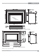
DIMENSIONS Note: Oversize faceplate is 44" x 28" (1118 mm x 711mm) 23-15/16 (607mm) 22 (559mm) 14-7/8 (378mm) 10-7/8” (276mm) 27-15/16 (710mm) 35-15/16 (912mm) 40-3/4 (1036mm) Low Profile Faceplate Dimensions * Standard size shown, custom size also available.
TABLE OF CONTENTS OPERATING INSTRUCTIONS Unit Dimensions ........................................................3 Safety Label...............................................................5 INSTALLATION For Your Safety ..........................................................7 Specifications ............................................................8 Installation into a Solid Fuel Fireplace .......................8 General Safety Information........................................
This is a copy of the labels that accompany each U31-3Gas Insert. We have printed a copy of the contents here for your review. The safety label is located on a plate inside the base of the unit visible when the bottom louver is opened. NOTE: FPI units are constantly being improved. Check the label on the unit and if there is a difference, the label on the unit is the correct one.
REQUIREMENTS MA Code - CO Detector (for the State of Massachusetts only) 5.08: Modifications to NFPA-54, Chapter 10 (2) Revise 10.8.
INSTALLATION FOR YOUR SAFETY This appliance requires air for proper combustion. Always provide adequate combustion and ventilation air. Follow instructions and information in CSA B149.1 (in Canada) or the National Fuel Gas Code ANS Z223.1/NFPA (in the USA), regarding requirements for combustion and ventilation air. INSTALLATION AND REPAIR SHOULD BE DONE BY AN AUTHORIZED SERVICE PERSON. THE APPLIANCE SHOULD BE INSPECTED BEFORE USE AND AT LEAST ANNUALLY BY A PROFESSIONAL SERVICE PERSON.
INSTALLATION IMPORTANT: SAVE THESE INSTRUCTIONS The Regency Gas Insert must be installed in accordance with these instructions. Carefully read all the instructions in this manual first. Consult the building authority having jurisdiction to determine the need for a permit prior to starting the installation. NOTE: Failure to follow the instructions could cause a malfunction of the heater which could result in death, serious bodily injury, and/or property damage.
INSTALLATION INSTALLATION CHECKLIST The Regency Gas Insert is installed as listed below. 1) Unit Location - check Clearances to Combustibles. MINIMUM FIREPLACE DIMENSIONS The minimum fireplace dimensions for the FPI gas fireplace insert are shown in the following diagrams: 2) Make the gas connections. Convert to Propane Gas if necessary. 3) Install the flue or liner to the sliding draft hood. CLEARANCES TO COMBUSTIBLES Sides Ceiling Mantle From Unit A 10" / 255 mm B 47.
INSTALLATION Conversion Kit from Natural Gas to Propane Model #404-969 for: U31-NG3 Units THIS CONVERSION MUST BE DONE BY A QUALIFIED GAS FITTER IF IN DOUBT DO NOT DO THIS CONVERSION !! 1) Turn the unit off and allow it to cool to room temperature. 8) Turn control knob to the “OFF” position 14) Verify that if the conversion is from NG to LPG, the screw must be re-assembled with the red o-ring visible (Fig. 5). 2) Unplug or disconnect power source to stove.
INSTALLATION GAS CONNECTION GAS CONNECTION WARNING: Only persons licensed to work with gas piping may make the necessary gas connections to this appliance. 1) If the appliance is to be installed into an existing chimney system, thoroughly clean the masonry or factory built fireplace. 2) The appliance is provided with an opening on the left hand side of the control compartment. A 1/2" gas supply pipe must be brought near this inlet hole. (See Diagram 3 on page 11).
INSTALLATION the setting should be within the limits specified. Check for proper draft by placing a match close to the draft check opening. This should be checked after the unit GAS INSERT AERATION SYSTEM OPTIONAL BRICK PANEL 1) Unwrap the brick pattern panels from the protective wrapping. 2) Remove the glass front if it is already installed. The aeration adjustment rod is attached to the air shutter which is located just above the orifice bracket.
INSTALLATION LOG SET INSTALLATION Read the instructions below carefully and refer to the diagrams. If logs are broken do not use the unit until they are replaced. Broken logs can interfere with the pilot operation.
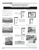
INSTALLATION 5) Place the Middle Left Log C)02-56 on the two pins as shown. 7) Place the notch in Center Log E)02-47 over Log B)0245 and across the cutout on Log A)02-43. E)02-47 A)02-43 C)02-56 B)02-45 Notch Cutout Logs A)02-43, C)02-56, and B)02-45 in position Logs D)02-46 and E)02-47 in position. 6) Place the Left Top Log D)02-46 on the pin on Log C)02-56 and on top of the cutout on Log A)02-43.
INSTALLATION Front edge of rear burner 10) Place the embers and Rockwool on the exposed front burner tray. A)02-43 B)02-45 F)02-48 Side View Bracket The bottom right edge of Log F)02-48 must sit snugly against the bracket and the front edge of the rear burner. 11) Separate platinum embers and place on and around the embers and rockwool on the burner tray. Avoid stacking platinum embers. 9) Place Front Left Log G)02-44 onto the 2 front pins as shown.
INSTALLATION FACEPLATE & TRIM INSTALLATION 1) Lay the faceplate panels flat, face down on something soft so they don't scratch. 2) Take the top faceplate and align the holes in it with the holes in the side panels. Using the screws provided, attach from the top of the panel (the holes in the top panel are slightly larger than the holes in the side panel to facilitate easier installation). Diagram 1.
INSTALLATION FLUSH FRONT INSTALLATION 1) Install Logs before going on to the next step. See the Log Installation instruction sheet or page 9. MESH GUARD INSTALL Line up hooks on mesh guard with slots on unit. Slide mesh guard down into slots until securely in place. FLUSH LOUVERS 1) The Top Louver is held in place by friction fit, if the Louver needs to be adjusted; bend the bracket out as shown in the diagram. 2) Install the bottom glass trim by hooking the trim into the lip on the firebox base.
INSTALLATION WIRING DIAGRAM This heater does not require a 120V A.C. supply for operation. In case of a power failure, the burner switch and the optional remote control/thermostat will continue to operate. However, a 120V A.C. power supply is needed for the fan/blower operation. CAUTION: Label all wires prior to disconnection when servicing controls. Wiring errors can cause improper and dangerous operation.
INSTALLATION FULL SCREEN FRONT 1) Hold the full screen door up against the unit in order to make the following wire connections. 3) Completely secure the full screen door to the unit by securing 4 screws to the Left and Right Side Trims. Pull the ON/OFF connector wires from the firebox and connect them to the switch. Connect the fan switch wires with the wire connectors from the fan speed control. Place clips over wires and tuck into side trim. .
INSTALLATION EXCALIBUR SURROUND INSTALLATION IMPORTANT NOTE: When using the Surround, the unit must be set 1" further into the fireplace than the standard faceplate installation. See the diagrams below for the correct minimum fireplace opening requirements. 2) Align the cut-outs in the Blanking Plate with the pins located on the inside top of the firebox. Slide the Blanking Plate into position ensuring it goes under the 2 flanges.
INSTALLATION 4) Secure the Faceplate by sliding the slots in the Faceplate into the flanges on the left and right side Faceplate Trim Brackets. Once the Faceplate is in place secure using 2 screws per side. 5) Place the bottom hooks of the Surround into the bottom slots of the Faceplate. Slightly pull up the Surround and push the top hooks into the top slots of the Faceplate. Push down to secure. Tug on the Surround to ensure it is securely locked in place.
INSTALLATION LOW PROFILE FACEPLATE INSTALLATION 1) Attach the inner faceplate panel to the insert body using 4 screws in the locations shown below. 4) Tuck the wires into the clip to keep them away from the insert using the clip provided. Attach the clip to the rear of the faceplate to ensure that the wires do not touch the side of the unit. The power cord should be run behind the inner faceplate panel.
INSTALLATION 7) Clip the right side air chamber clip as shown below in Diagram 8. 10) Hook door frame on 2 pins over glass door in locations shown below in Diagram 11. Diagram 8 8) Attach 2 brackets near the bottom of the unit with one screw as shown below in Diagram 9 (left and right brackets are interchangeable. Diagram 9 9) Diagram 11 11) Take the outer faceplate, line up the openings on the left and right legs and install onto the inner faceplate panel pins.
OPERATING INSTRUCTIONS OPTIONAL WALL THERMOSTAT A wall thermostat may be installed if desired. Connect the wires as per the wiring diagrams. Note that the wires are connected to the "TH" on the gas valve. Use table on page 14 to determine the maximum wire length: Note: Preferable if the thermostat is installed on an interior wall. FPI offers an optional programmable thermostat but any 250-750 millivolt rated non-anticipator type thermostat that is CSA, ULC or UL approved may be used.
OPERATING INSTRUCTIONS INSTALLATION SHUTDOWN PROCEDURE COPY OF LIGHTING INSTRUCTION PLATE 1) Use the rocker switch to turn off the main burner. 2) Open the bottom louver assembly. 3) Push in the gas control knob slightly and turn clockwise to "OFF". Do not force. 4) Disconnect all electric power and gas to the appliance if service is to be performed. FIRST FIRE The first fire in your stove is part of the paint curing process.
MAINTENANCE are temperature changes within the unit these sounds will likely re-occur. Again, this is normal for steel fireboxes. 5) Keep the area near the appliance clear and free from combustible materials, gasoline and other flammable vapours and liquids. Blower Thermodisc: When this thermally activated switch turns ON it will create a small "clicking" sound. This is the switch contacts closing and is normal.
MAINTENANCE FAN MAINTENANCE DOOR GLASS REPLACEMENT Your Regency insert is supplied with high temperature, 5 mm Neoceram ceramic glass that will withstand the highest heat that your unit will produce. In the event that you break your glass by impact, purchase your replacement from an authorized FPI dealer only, and follow our step-by-step instructions for replacement. WARNING: do not operate appliance with the glass front removed, cracked or broken.
PARTS LIST Main Assembly Part # Description Part # 1) 400-011 Fan Opening Cover 2) 911-071/P 5) 910-750 910-752 Fan Motor (120 V) Power Cord (120 V) Wire Harness (intermediate) 6) * 7) * 8) 910-142 10) * 11) * 12) 910-220 13) * 16) * 17) * 18) * 19) * 20) 400-024 Thermodisc cover Thermodisc bracket Thermodisc-Fan Auto ON/OFF Drafthood Assembly Spill Switch Bracket Spill Switch Levelling Bolts 5/16 x 3 Hex Head Cable Tie Wire Holder Clip Strain Relief Grommet for Power Cord Air Channel 21) 402-922 4
PARTS LIST Burner Assembly & Log Set Part # Description 404-574/P 404-576/P 52) 910-568 53) 910-190 54) * Valve Assembly - NG Valve Assembly - LP SIT 820 Valve -NG/LP** Piezo Ignitor and nut Valve Heat Shield 56) * Pilot Bracket 57) 904-240 904-593 904-390 904-345 60) 402-526 Burner Orifice Nat. Gas #37 Burner Orifice Nat. Gas #40 (High Altitude) Burner Orifice LP # 52 Burner Orifice Nat.
PARTS LIST Flush Front Assembly Part # Flush Door 402-515/P 150) 936-243 153) * 154) * 155) 402-046 156) 936-238 157) * 158) 402-033 159) 936-233 Description Complete Flush Front Door Frame Gasket - 7/8" Glass Side Trim Flush Glass Glass Support Trim - Black Flush Glass Gasket Screw #10-24 x 1/2" Flush Glass Bracket 3/4" Rope Gasket *Not available as a replacement part.
PARTS LIST Faceplate Assembly Part # Description 402-919 41) * 42) * 43) * 402-534 44) * 45) * 46) * Complete Faceplate (Set) with Black Trim - Oversize Faceplate Side Right - Oversize Faceplate Top - Oversize Faceplate Side Left Assy-Oversize Trims Pkg.
PARTS LIST 32 Regency U31-3 Gas Fireplace Insert
PARTS LIST LOW PROFILE FACEPLATE Part # 403-954 1) 2) 3) 4) 5) * * * * * Description Back plate Assembly Bottom Louver Right mounting bracket Left mounting bracket Front Frame 5 4 1 2 3 Regency U31-3 Gas Fireplace Insert 33
NOTES 34 Regency U31-3 Gas Fireplace Insert
WARRANTY Regency® Fireplace Products are designed with reliability and simplicity in mind. In addition, our internal Quality Assurance Team carefully inspects each unit thoroughly before it leaves our facility. FPI Fireplace Products International Ltd. is pleased to extend this limited lifetime warranty to the original purchaser of a Regency® Product. This warranty is not transferable.
Register your Regency® warranty online www.regency-fire.com Reasons to register your product online today! • View and modify a list of all your registered products. • Request automatic email notification of new product updates. • Stay informed about the current promotions, events, and special offers on related products.