Owners & Installation Manual Freestanding Woodstove Vancouver Model: F2402M PLEASE KEEP THESE INSTRUCTIONS FOR FUTURE REFERENCE WARNING: Improper installation, adjustment, alteration, service or maintenance can cause injury or property damage. Refer to this manual. For assistance or additional information consult an authorised installer, service agency or the gas supplier. FOR YOUR SAFETY Do not store or use gasoline or other flammable vapours and liquids in the vicinity of this or any other appliance.
Thank-you for purchasing a REGENCY FIREPLACE PRODUCT. The pride of workmanship that goes into each of our products will give you years of trouble-free enjoyment. Should you have any questions about your product that are not covered in this manual, please contact the REGENCY DEALER in your area. Keep those REGENCY FIRES burning. SAFETY NOTE: If this woodstove is not properly installed, a house fire may result.
TABLE OF CONTENTS THE REGENCY FREESTANDING WOOD STOVE SAFETY LABEL Optional Accessories Installation - Pedestal Ash Drawer Kit ............................................16 Copy of Data Badge ..............................................................4 - Bottom Shield Ashdrawer Kit .....................................16 - Screen Door ...............................................................16 INSTALLATION - Blower/Fan .................................................................
SAFETY LABEL This is a copy of the label that accompanies each Regency Freestanding Woodstove (F2402M). We have printed a copy of the contents here for your review. 4 NOTE: Regency units are constantly being improved. Check the label on the unit and if there is a difference, the label on the unit is the correct one.
UNIT DIMENSIONS 27-3/8” (695mm) 24-7/8” (632mm) 6-5/8” (168mm) Regency Freestanding Woodstove 29-1/8" (740mm) 30-3/8" (772mm) 24” (610mm) 5
INSTALLATION RESIDENTIAL INSTALLATION 1) Please read this entire manual before you install and use your new woodstove. Failure to follow instructions may result in property damage, bodily injury or even death. Be aware that local Codes and Regulations may override some items in this manual. Check with your local inspector. 2) Select a position for your Regency Stove. Consult the minimum clearance chart for your model and set the stove in place.
INSTALLATION AUSTRALIA ONLY IMPORTANT The Regency F2402M has been tested with the flue kits listed below. A default flue kit as listed in AS/NZS 2918:2001 may also be used. Use only the instructions and clearance dimensions on this page for heaters to be installed in Australia. The Regency F2402M has been tested by the AHHA Testing Laboratory and conforms to AS/NZS 2918:200, Report No. ATL19-04. These are the only flue kits certified for use with this heater for installation in Australia.
INSTALLATION Minimum Alcove Clearance to Combustible Materials The Regency Freestanding models have been alcove approved and must be installed with a listed double wall connector to the ceiling level. Note: Minimum alcove ceiling height - 84" (2134mm) Maximum depth of alcove - 36" (914mm) From Unit Unit From Flue Center-line G Medium F2402M with Airmate 15" (381 mm) with Rear Deflector 15" (381 mm) H I Min. Width J 5.5" (139 mm) 27" (685 mm) 6.
INSTALLATION STOVE ASSEMBLY PRIOR TO INSTALLATION All units require either the pedestal or 4 legs attached to the base. The F2402M stove requires either the Airmate or Rear Heat Deflector on top of the stove. Clearances to combustible materials vary depending on whether the airmate or rear heat deflector is installed, so be sure to check the clearance information on pages 7 and 8.
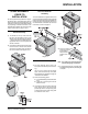
INSTALLATION Leg and Bottom Shield Assembly The instructions below apply to the steel leg, painted cast leg and the gold plated cast leg. It will be easier to attach the legs to the stove if the stove is tipped on its back (preferably on a soft surface to prevent scratching). Ensure to be extremely careful when tipping stove. 1) Remove the 4 bolts from underside of the base of the pedestal and discard. Also remove cover plate and put to the side. 2) Line up the heat shield with the bottom of the unit.
INSTALLATION MASONRY CHIMNEY Ensure that a masonry chimney meets the minimum standards of the National Fire Protection Association (NFPA) by having it inspected by a professional. Make sure there are no cracks, loose mortar or other signs of deterioration and blockage. Have the chimney cleaned before the stove is installed and operated. When connecting the stove through a combustible wall to a masonry chimney, special methods are needed.
INSTALLATION COMBUSTIBLE WALL CHIMNEY CONNECTOR PASS-THROUGHS Minimum chimney clearance to brick and combustibles 2 in. (50.8mm) Using a minimum thickness 3.5" (89 mm) brick and a 5/8" (15.9 mm) minimum wall thickness clay liner, construct a wall pass-through. The clay liner must conform to ASTM C315 (Standard Specification for Clay Fire Linings) or its equivalent. Keep a minimum of 12" (304.8 mm) of brick masonry between the clay liner and wall combustibles.
INSTALLATION RECOMMENDED HEIGHTS FOR WOODSTOVE FLUE Simple rules on draft. See Table 1. 3) Add 4% overall for each 1000' (3.5m) above sea level. 1) At sea level minimum height is 12' (3.7m) Example: a) straight. 1-1/2 ft. of horizontal run one "T" 2) Add the following vertical height to compenTotal Addition (at sea level) sate for: 45 deg. elbow = 1 ft. (.3m) Example: b) 90 deg. elbow = 2 ft. (.6m) One 90 deg. elbow "T" = 3 ft. (.9m) 2 ft. of horizontal run Each foot of horizontal run = 2 ft. (.
INSTALLATION MOBILE HOME INSTALLATION Once you have properly marked the position of your unit and the floor protection as outlined in the Residential Installation items #1 through #8, a supply of fresh air has to be supplied to your unit. Cut a minimum 4 inch diameter hole through your floor protector and the floor directly under your pedestal base to the outside. Use 4" duct pipe with a mesh grill to pipe fresh air into the pedestal area.
INSTALLATION LISTED COMPONENTS FOR MOBILE HOME INSTALLATION SIMPSON DURA-PLUS Qty.Part # Description 1 6DVL8693 Connector Kit 1 6DP-MH9096 Mobile Home Kit side with the air holes facing toward the door. Slide the tube into the left hand side, as far as possible and then bring it back into the hole on the right hand side until it locks into position. If the tube will not slide in easily, simply use a pair of vise grips or pliers and tap it into place with a hammer.
INSTALLATION BRICK INSTALLATION Firebrick is included to extend the life of your stove and radiate heat more evenly. Check to see that all firebricks are in their correct positions and have not become misaligned during shipping. STEP-BY-STEP OPTIONAL ACCESSORIES INSTALLATION The "AD" brick in the drawings above is the brick covering the Ash Dump hole that is used when the Ash Drawer Kit is installed. The pieces listed below can be purchased and installed during the initial installation or added on later.
INSTALLATION Blower/Fan 1) Remove the two screws from the top of the fan housing. 2) Slide the fan up into the rear heat shield. 3) After aligning holes, secure the fan to the rear heat shield using the two screws removed earlier. CAUTION: The connection cord should not be in contact with any hot surfaces. Do not route cord under or in front of unit. Read the operating instructions for the fan before using. See Page 19.
OPERATING INSTRUCTIONS OPERATING INSTRUCTIONS With your unit now correctly installed and safety inspected by your local authority, you are now ready to start a fire. Before establishing your first fire, it is important that you fully understand the operation of your draft control. WARNING Fireplace Stoves equipped with doors should be operated only with doors fully open or doors fully closed.
OPERATING INSTRUCTIONS FAN OPERATION Automatic To operate the fan automatically, push the bottom switch on the side of the fan housing to "AUTO" and the top switch to either "HIGH" or "LOW" for fan speed. This will allow the fan to turn on as the stove has come up to operating temperature. It will also shut the fan system off after the fire has gone out and the unit cooled to below a useful heat output range.
MAINTENANCE MAINTENANCE It is very important to carefully maintain your fireplace stove, including burning seasoned wood and maintaining a clean stove and chimney system. Have the chimney cleaned before the burning season and as necessary during the season, as creosote deposits may build up rapidly. Moving parts of your stove require no lubrication.
PARTS LIST STOVE MAIN ASSEMBLY Part # 1) 3) 4) 5) 6) 7) 9) 12) 13) 14) 15) 16) 17) 19) 20) Description 846-913 846-915 Door Assy-Med Gold F2402M (no glass) Door Assy-Med Black F2402M (no glass) 846-302 936-243 820-184 * 948-170/P 846-973 820-375 * 820-376 * 846-570 846-918 948-101 948-102 Glass - Replacement - F2402M 7/8" Adhesive Tape Gasket Glass Retainer Clips (8/set) Screw - 1/4 - 20 x 3/8" Small Glass Retainer F2402M Door Handle Assembly Ash Hole Cover Plate Bolt 1/4 - 20 x 1/2 Hex Head Retainer
PARTS LIST PEDESTAL, BOTTOM SHIELD & LEG OPTIONS Part # Description 48) 49) 50) 020-915 904-257 * Pedestal - Medium Large Magnet Catch Blanking Plate - Pedestal 45) 46) 58) 59) 850-100 * * 942-110 820-249 Ashdrawer Kit - Pedestal Ashdrawer - Pedestal Ashdrawer Lid Assy Ash Plug Ash Plug Tool Handle 56) 57) 020-911 * Bottom Shield - Medium Blanking Plate - Btm Shield 55) 58) 59) 850-101 * 942-110 820-249 Ashdrawer Kit - Btm Shield Ashdrawer - Bottom Shield Ash Plug Ash Plug Tool Handle 140) 850
PARTS LIST FIREBRICK Part # 70) 74) 75) 76) 902-111 802-147 802-122 802-152 Description Brick - Regular Full Size: 1-1/4" x 4-1/2" x 9" Brick Partial: 1-1/4" x 4-1/2" x 3-1/2" Brick Partial: 1-1/4" x 4-1/2" x 2" Brick Partial: 1-1/4" x 2" x 9" Regency Freestanding Woodstove 23
NOTES 24 Regency Freestanding Woodstove
NOTES Regency Freestanding Woodstove 25
NOTES 26 Regency Freestanding Woodstove
WARRANTY Regency Fireplace Products are designed with reliability and simplicity in mind. In addition, our internal Quality Assurance Team carefully inspects each unit thoroughly before it leaves our door. FPI Fireplace Products International Ltd. is pleased to extend this limited lifetime warranty to the original purchaser of a Regency Product. This warranty is not transferable.
DISTRIBUTORS: Western Australia AUSTRALIAN HEATING DISTRIBUTORS 31 CLUNE STREET BAYSWATER, WA 6053 Eastern Australia FIREPLACE PRODUCTS AUSTRALIA PTY. LTD. 21-23 SOUTH LINK BLVD. DANDENONG, VIC 3175 SERVICE AGENTS: HEARTH HOUSE SERVICE 31 CLUNE STREET BAYSWATER, WA 6053 NOTE: PLEASE RETAIN YOUR INVOICE AS PROOF OF PURCHASE FOR WARRANTY VERIFICATION INCORRECT INSTALLATION OR GAS PRESSURE SETTINGS ARE NOT COVERED BY WARRANTY A SERVICE OR CALLOUT FEE WILL BE CHARGED IN THESE CIRCUMSTANCES.