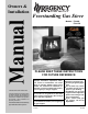
Owners & Installation Manual Freestanding Gas Stove LISTINGS AND CODE APPROVALS These gas appliances have been tested in accordance with AG 103, NZS 5262 and have been certified by the Australian Gas Association for installation and operation as described in these Installation and Operating Instructions. Your unit should be serviced annually by an authorised service person.
To the New Owner: Congratulations! You are the owner of a state-of-the-art Regency® Room Sealed Gas Stove by FPI Fireplace Products International Ltd. The Regency® Gas Series of hand crafted appliances has been designed to provide you with all the warmth and charm of a woodstove, at the flick of a switch. The models F39-NG and F39-LPG of this series has been approved by Warnock Hersey for both safety and efficiency.
TABLE OF CONTENTS Unit Specifications .........................................................2 SAFETY LABEL Safety Label ..................................................................4 INSTALLATION Important .......................................................................5 Specifications ................................................................5 Before You Start ............................................................5 General Safety Information .....................................
SAFETY LABEL This is a copy of the label that accompanies each REGENCY F39 Room Sealed Freestanding Gas Stove. We have printed a copy of the contents here for your review. The data plat is located on the inside of the drop down pedestal door. NOTE: Regency® units are constantly being improved. Check the label on the unit and if there is a difference, the label on the unit is the correct one.
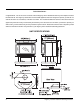
INSTALLATION IMPORTANT SAVE THESE INSTRUCTIONS The REGENCY Room Sealed Freestanding Gas Stove must be installed in accordance AG601 and NZS 5261 and with these instructions. Carefully read all the instructions in this manual first. Consult the building authority having jurisdiction to determine the need for a permit prior to starting the installation. Note: Failure to follow the instructions could cause a malfunction of the heater which could result in death, serious bodily injury, and/or property damage.
INSTALLATION 10) Be aware of electrical wiring locations in walls and ceilings when cutting holes for termination. 11) Under no circumstances should this appliance be modified. Parts that have to be removed for servicing should be replaced prior to operating this appliance. 12) Installation and any repairs to this appliance should be done by an authorised service person. An authorised service person should be called to inspect this appliance annually.
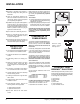
INSTALLATION For flue termination requirements, refer to "Exterior Flue Termination Location" section. COMBUSTION AND VENTILATION AIR The combustion air from this appliance is drawn from outside the building through the outer flue. Extra provision for combustion air inside the room is not required. LOUVER INSTALLATION 1) Attach the top & bottom louvres to the side stove panel using 2 screws per side.
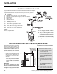
INSTALLATION EXTERIOR FLUE TERMINATION LOCATIONS Minimum clearances required for balanced flue terminals or the flue terminals of outdoor appliances according to AG 601 (AGA gas installation code) or NZS 5261 (New Zealand) a b c d e f g h j k Minimum Clearance (mm) Below eaves, balconies or other projections: - Appliances up to 50 MJ/h input 300 - Appliances over 50 MJ/h input 500 From the ground or above a balcony 300 From a return wall or external corner 500 From a gas meter (M) 1000 From an electrici
INSTALLATION FLUING ARRANGEMENTS Horizontal Terminations for All Fluing Systems The shaded areas in the diagram below show all allowable combinations of vertical runs with horizontal terminations. Maximum one 90O elbow (two 45o elbows equal one 90o elbow). LPG and NG: Residential, Manufactured and Mobile Homes Installations The fluing arrangements diagrammed below, have a min. of 75% (flue loss) efficiency with Fan Off, as required for manufactured homes.
INSTALLATION DV STOVE HORIZONTAL FLUE KIT Horizontal Stove Flue Kit (Part # 946-112) includes all the parts needed to install the F39 Freestanding Gas unit with minimum horizontal and vertical vent dimensions. For installations that require longer vertical and/or horizontal vents use the Dura-Vent system as shown in your manual. Qty. Description 1) 2 Rigid Pipe Section 1.
INSTALLATION when cut will seat onto both the starter collar and the 90o elbow. Crimped section of rigid pipe seats into the 90o elbow. Only cut the uncrimped side of pipe. Dismantle all pipe sections including flue terminal. 3) Attach the 4" dia. flex liner to the flue terminal ensuring that the flex overlaps the collar of the flue terminal by a minimum of 1-3/8"(35mm). Use Mill-Pac to seal and secure with 3 of the #8 x 1/2" screws (stainless steel). 4) Attach the 2 ft.
INSTALLATION DURA-FLUE TERMINATION KIT Planning Your Dura-Flue Installation There are two basic types of Dura-Flue Room Sealed System installations: horizontal termination and vertical termination. Confirm the maximum horizontal run and maximum vertical rise from the diagrams, refer to "Fluing Arrangements" section. When planning your installation, it will be necessary to select the proper length of flue pipe for your particular requirements.
INSTALLATION 945B 945G 945BG 990 990B 990G 990BG 991 980 982 981 940 941 3951 963 943 943S 953 950 988 942 45O Elbow-Black 45O Elbow-Swivel Galv. 45O Elbow-Swivel-Black 90O Elbow Galv. 90O Elbow-Black 90O Elbow-Swivel Galv. 90O Elbow-Swivel-Black High Wind Term. Cap (Vertical) Vertical Term. Cap Snorkel-14" Rise Term.Cap Snorkel-36" Rise Term.
INSTALLATION 6) Continue to assemble pipe lengths. Note: If an offset is necessary in the attic to avoid obstructions, it is important to support the flue pipe every 3 feet, to avoid excessive stress on the elbows, and possible separation. Wall straps are available for this purpose. See diagram 7. Galvanized pipe and elbows may be utilized in the attic as well as above the roofline. The galvanized finish is desirable above the roofline due to its higher corrosion resistance.
INSTALLATION sions, in the same manner as shown in diagram 10. 1) Situate the chimney in a convenient location as near as possible to the appliance outlet. Cut and frame a hole in the roof for the support. The sides of this hole must be vertical with 1 1/4" clearance. 2) Place the support in the opening. Lower it to the correct height as determined by the table and diagram below.
INSTALLATION Note: To properly check gas pressure, both inlet and manifold pressures should be checked using the valve pressure ports on the valve. AERATION ADJUSTMENT 1) Make sure the valve is in the "OFF" position. The burner aeration is factory set but may need adjusting due to either the local gas supply or altitude. 2) Loosen the "IN" and/or "OUT" pressure tap(s), turning counterclockwise with a 1/8" wide flat screwdriver.
INSTALLATION CONVERSION KIT #731-968 FROM NG TO LPG THIS CONVERSION MUST BE DONE BY AN AUTHORIZED GAS FITTER IF IN DOUBT DO NOT DO THIS CONVERSION !! Conversion Kit Contains: Qty. 1 1 1 Part # 904-390 904-529 918-590 1 1 908-528 910-037 1 918-484 Description Burner Orifice #52 5/32" Allen Key Label "Converted to LPG" Red "LPG" label LPG Injector (Pilot Orifice) Instruction Sheet 8) Remove burner orifice with a 1/2" wrench. Use another wrench to hold on to the elbow behind the orifice.
INSTALLATION LOG SET INSTALLATION CONVERSION TO LOWER BTU RATING THIS CONVERSION MUST BE DONE BY AN AUTHORIZED GAS FITTER IF IN DOUBT DO NOT DO THIS CONVERSION !! NG Conversion Kit 730-920 Contains: Qty. Part # Description 1 904-240 Burner Orifice #37 (NG) 1 918-034 Decal "Converted to 30,000 Btu" 1 918-033 Instruction Sheet 6) Remove burner orifice with a 1/2" spanner and discard. The gas log kit contains the following: LPG Conversion Kit 730-922 Contains: Qty.
INSTALLATION 3) Place Rear Log A)02-65 on the two pins on the rear log support. 7) Place the Left Top Log D)02-46 on the pin on Log B)02-56 and on top of the cutout on Log A)02-65. 11) Position notch in Front Right Log G)02-48 on Log F)02-47 and push the bottom right edge against the bracket on the burner tray. G)02-48 A)02-65 A)02-65 A)02-65 F)02 -4 7 D)02-46 B)02-56 C)02-44 E)02-45 Pins on Rear Log Support Cutout Pin 4) Place the Middle Left Log B)02-56 on the two pins as shown.
INSTALLATION OPTIONAL WALL THERMOSTAT FRONT DOOR INSTALLATION (packaged separately) A wall thermostat may be installed if desired. Connect the wires as per the wiring diagrams. Note that the wires are connected to the "TH" on the gas valve. Use table below to determine the maximum wire length: 1) Open the two side panels. 2) Slide the door onto the two hinge pins making sure the two pieces are flush togethSee diagram 1. 3) Close the door. The latch plate must be centered around the alignment pin.
INSTALLATION WIRING This heater does not require a 240V A.C. supply for the gas control to operate. A 240V A.C. power supply is needed for the fan/blower operation. Caution: Ensure that the wires do not touch any hot surfaces and are away from sharp edges. CAUTION: Label all wires prior to disconnection when servicing controls. Wiring errors can cause improper and dangerous operation.
OPERATING INSTRUCTIONS OPERATING INSTRUCTIONS 4) Turn the PILOT knob counterclockwise to pilot and align it with the arrow as shown in diagram above. Before operating this appliance, proceed through the following check list. 5) Push in PILOT knob all the way in and hold. Immediately push IGNITOR button until pilot lights. Continue to hold the PILOT knob in for approximately one minute, then release the PILOT knob. The pilot flame should continue to burn.
OPERATING INSTRUCTIONS COPY OF THE LIGHTING PLATE INSTRUCTIONS FOR YOUR SAFETY READ BEFORE LIGHTING This appliance must be installed in accordance with local codes, if any; if none, follow the National Fuel Gas Code, ANSI Z223.1/NFPA 54, or Natural Gas and Propane Installation Codes, CSA B149.1. (Australia: AS5601-2004, New Zealand: NZS 5261) WARNING: If you do not follow these instructions exactly, a fire or explosion may result causing property damage, personal injury or loss of life.
MAINTENANCE MAINTENANCE INSTRUCTIONS 1) Always turn off the valve before cleaning. For relighting, refer to lighting instructions. Keep the burner and control compartment clean by brushing and vacuuming at least once a year. When cleaning the logs, use a soft clean paint brush as the logs are fragile and easily damaged. 2) Clean glass (never when unit is hot), appliance, louvres, and door with a damp cloth. Never use an abrasive cleaner.
MAINTENANCE LOG REPLACEMENT The unit should never be used with broken logs. Turn off the gas valve and allow the unit to cool before opening door to carefully remove the logs. The pilot light generates enough heat to burn someone. If for any reason a log should need replacement, you must use the proper replacement log. The position of these logs must be as shown in the diagram under Log Installation.
MAINTENANCE 7) Tighten side panels nuts using the following procedure: a. tighten top & bottom outside corner nuts (2) b. tighten inside nuts (3) c. tighten top & bottom inside corners (2) 8) Tighten the 10 nuts on center glass retainer. To remove F39 fan: 1) Unplug or disconnect power source to stove. 2) Remove all logs and the rear log support, then remove the 10 screws holding the access panel in place. 9) Repeat step 7 for other side panel. 3) Unclip the black and white wires from the fan motor.
MAINTENANCE REMOVING VALVE If your valve requires maintenance or replacement, use the following instructions: 4) Remove the two outside frame pieces by removing two screws per side. See diagram below. 10) To replace the burner tray assembly, simply reverse these instructions. Note: Always close off the gas supply before removing the valve. 1) Open front pedestal door. You may want to put a soft cloth on the base of the unit so that when the pedestal door is open it doesn't scratch the paint.
PARTS LIST F39 MAIN ASSEMBLY Part # 1) 4) 8) 560-920 730-038 730-560 10) 730-034 Description Louver Assy - Gold (Set) Door Screen (Austraila only) Relief Door Assembly (with gasket) Mounting Plate Gasket Part # 31) 32) 33) 36) 630-021 730-028 630-520 936-194 37) 936-197 11) 730-519/P Fan Assembly (240 Volt) 910-169/P Fan Motor (240 Volt) 12) 910-714 Power Cord (240 Volt) 15) 16) 17) 18) 560-525 730-039 904-257 560-025 19) 730-530 20) 730-525 21) 560-031 23) 904-258 24) 948-255 25) * 26) * 27) 910-2
PARTS LIST F39 BURNER & LOG ASSEMBLY Part # 52) 54) 55) 56) 57) Description 910-190 910-373 910-372 918-088 * Piezo Ignitor & Nut Knob - Pilot Valve Extension Flame Adjusting Knob Control Plate Decal Switch Plate 730-574/P 910-378 904-688 936-170 Valve Assembly - NG Valve - S.I.T. - NG #32 Orifice - N.G. Orifice Gasket 66) 910-038 910-039 Pilot Assy - S.I.T. - 3 Flame NG Pilot Assy - S.I.T.
PARTS LIST F39 DOOR ASSEMBLIES Part # 101) 105) 106) 107) 108) 111) 112) 208) 730-924 730-926 730-932 730-928 650-920 * 940-323/P 936-243 940-322/P * 750-015 940-325/P Description Gold Mitred Door - Complete Black Mitred Door - Complete Gold Wrap Door - Complete Gold Panel Door - Complete Door Gasket Kit Ceramic Paper Side Glass Glass Gasket Centre Glass Door Frame Fibre Paper Door Glass Extrusion Wrap Glass *Not available as a replacement part.
WARRANTY Regency Fireplace Products are designed with reliability and simplicity in mind. In addition, our internal Quality Assurance Team carefully inspects each unit thoroughly before it leaves our door. Regency Industries Ltd. is pleased to extend this limited lifetime warranty to the original purchaser of a Regency Product.