Freestanding Gas Stove Manual Owners & Installation LISTINGS AND CODE APPROVALS These gas appliances have been tested in accordance with AS4553-2000, NZS 5262 and have been certified by the Australian Gas Association for installation and operation as described in these Installation and Operating Instructions. Your unit should be serviced annually by an authorised service person.
To the New Owner: Congratulations! You are the owner of a state-of-the-art Regency Room Sealed Gas Stove by FPI Fireplace Products International Ltd. The Regency Gas Series of hand crafted appliances has been designed to provide you with all the warmth and charm of a woodstove. The models FG39-NG and FG39-LPG of this series has been approved by AGA. As it also bears our own mark, it promises to provide you with economy, comfort and security for many trouble free years to follow.
TABLE OF CONTENTS Page Safety Label Safety Label ............................................................ 4 Installation Specifications .......................................................... 5 Before You Start ...................................................... 5 General Safety Information ....................................... 5 Installation Checklist ................................................ 6 Clearances to Combustibles ....................................
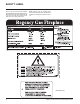
SAFETY LABEL This is a copy of the label that accompanies each REGENCY FG39 Freestanding Gas Stove. We have printed a copy of the contents here for your review. The data plat is located on the inside of the drop down pedestal door. NOTE: Regency units are constantly being improved. Check the label on the unit and if there is a difference, the label on the unit is the correct one.
INSTALLATION IMPORTANT: SAVE THESE INSTRUCTIONS The REGENCY Room Sealed Freestanding Gas Stove must be installed in accordance AG601 and NZS 5261 and with these instructions. Carefully read all the instructions in this manual first. Consult the building authority having jurisdiction to determine the need for a permit prior to starting the installation. Note: Failure to follow the instructions could cause a malfunction of the heater which could result in death, serious bodily injury, and/or property damage.
INSTALLATION 10) Be aware of electrical wiring locations in walls and ceilings when cutting holes for termination. 11) Under no circumstances should this appliance be modified. Parts that have to be removed for servicing should be replaced prior to operating this appliance. 12) Installation and any repairs to this appliance should be done by an authorised service person. An authorised service person should be called to inspect this appliance annually.
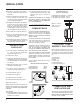
INSTALLATION LOUVER INSTALLATION 1) Attach the top & bottom louvres to the side stove panel using 2 screws per side. FLUEING INTRODUCTION INSTALLATION PRECAUTIONS The DV Stove Horizontal Flue Kit and the Simpson Dura-Flue Room Sealed System Model DVGS fluing systems, in combination with the Regency Room Sealed Freestanding Gas Stove, FG39-NG, and FG39-LPG, have been tested and listed as direct flue heater systems by AGA.
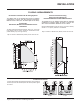
INSTALLATION EXTERIOR FLUE TERMINATION LOCATIONS Minimum clearances required for balanced flue terminals or the flue terminals of outdoor appliances according to AS5601-2004 (AGA gas installation code) or NZS 5261 (New Zealand) a b c d e f g h j k Minimum Clearance (mm) Below eaves, balconies or other projections: - Appliances up to 50 MJ/h input 300 - Appliances over 50 MJ/h input 500 From the ground or above a balcony 300 From a return wall or external corner 500 From a gas meter (M) 1000 From an ele
INSTALLATION FLUEING ARRANGEMENTS Horizontal Terminations for All Fluing Systems The shaded areas in the diagram below show all allowable combinations of vertical runs with horizontal terminations. Maximum one 90O elbow (two 45o elbows equal one 90o elbow). LPG and NG: Residential, Manufactured and Mobile Homes Installations The fluing arrangements diagrammed below, have a min. of 75% (flue loss) efficiency with Fan Off, as required for manufactured homes.
INSTALLATION DV STOVE HORIZONTAL FLUE KIT Horizontal Stove Flue Kit (Part # 946-112) includes all the parts needed to install the FG39 Freestanding Gas unit with minimum horizontal and vertical vent dimensions. For installations that require longer vertical and/or horizontal vents use the Dura-Vent system as shown in your manual. Qty. 1) 2 2) 1 3) 4 4) 1 5) 1 6) 1 7) 1 8) 2 9) 1 10) 12 11) 14 12) 4 Description Rigid Pipe Section 1.
INSTALLATION d) Cut the 2 ft. (.6m) section of rigid pipe to length. Ensure that the pipe length when cut will seat onto both the starter collar and the 90o elbow. Crimped section of rigid pipe seats into the 90o elbow. Only cut the uncrimped side of pipe. Dismantle all pipe sections including flue terminal. 3) Attach the 4" (102mm) dia. flex liner to the flue terminal ensuring that the flex overlaps the collar of the flue terminal by a minimum of 1-3/8"(35mm).
INSTALLATION DURA-FLUE TERMINATION KIT Planning Your Dura-Flue Installation There are two basic types of Dura-Flue Room Sealed System installations: horizontal termination and vertical termination. Confirm the maximum horizontal run and maximum vertical rise from the diagrams on page 9. When planning your installation, it will be necessary to select the proper length of flue pipe for your particular requirements.
INSTALLATION 963 943 943S 953 950 988 942 45O Elbow-Swivel-Black 90O Elbow Galv. 90O Elbow-Black 90O Elbow-Swivel Galv. 90O Elbow-Swivel-Black High Wind Term. Cap (Vertical) Vertical Term. Cap Snorkel-14" Rise Term.Cap Snorkel-36" Rise Term.
INSTALLATION 6) Continue to assemble pipe lengths. Note: If an offset is necessary in the attic to avoid obstructions, it is important to support the flue pipe every 3 feet, to avoid excessive stress on the elbows, and possible separation. Wall straps are available for this purpose. See diagram 7. Galvanized pipe and elbows may be utilized in the attic as well as above the roofline. The galvanized finish is desirable above the roofline due to its higher corrosion resistance.
INSTALLATION Notes: a) For multistorey vertical installations, a Ceiling Fire stop (Part # 963) is required at the second floor, and any subsequent floor. Diagram 13. The opening should be framed to 10 " x 10" (254mm x 254mm) inside dimensions, in the same manner as shown in diagram 10. nails Ceiling Firestop 1-1/4" (32mm) Min.
INSTALLATION GAS CONNECTION The gas line should be rigid pipe. Copper may also be used if approved by AS5601-2004. 7) Gas Outlet Pressure Electric Modulator 8) Pilot Outlet 9) Main Gas Outlet 10) Side Outlet The gas connection at the valve is 1/2 male. For minimum and maximum supply pressure see the System Data Table. GAS PIPE PRESSURE TESTING AERATION ADJUSTMENT 3) Attach manometer to "IN" and/or "OUT" pressure tap(s) using a 5/16" (8mm) ID hose.
INSTALLATION Conversion Kit for NG to LPG Model #736-969 THIS CONVERSION MUST BE DONE BY A QUALIFIED GAS FITTER IF IN DOUBT DO NOT DO THIS CONVERSION !! Conversion Kit 736-969 Contains: Qty. Part # 1 904-641 1 908-528 2 918-590 1 918-335 1 910-920 Description Burner Orifice #50 Red "LPG" label Label "Converted to LPG" Instruction Sheet Pilot Orifice 7) Lift the pilot assembly and remove the pilot tube using an 11mm wrench. Antenna Control Box Cover 1) Shut off the gas supply and unplug the power cord.
INSTALLATION A B C 21) Turn on the gas supply and plug in the power cord. 22) Adjusting the Outlet Pressure All the adjustments must be carried out in the following order: Remove the modulator plastic cap (A) using needle nose pliers. Maximum pressure: Turn the unit ON to its highest input rating. Screw in the nut (B) to increase the outlet pressure and screw it out to decrease it. Use a 10 mm wrench. NOTE: The outlet pressure must be set to maximum 2.65 kPa.
INSTALLATION LOG SET INSTALLATION CONVERSION TO LOWER BTU RATING THIS CONVERSION MUST BE DONE BY AN AUTHORIZED GAS FITTER IF IN DOUBT DO NOT DO THIS CONVERSION !! NG Conversion Kit 730-920 Contains: Qty. Part # Description 1 904-240 Burner Orifice #37 (NG) 1 918-034 Decal "Converted to 30,000 Btu" 1 918-033 Instruction Sheet 6) Remove burner orifice with a 1/2" spanner and discard. The gas log kit contains the following: LPG Conversion Kit 730-922 Contains: Qty.
INSTALLATION 3) Place Rear Log A)02-65 on the two pins on the rear log support. 7) Place the Left Top Log D)02-46 on the pin on Log B)02-56 and on top of the cutout on Log A)02-65. 11) Position notch in Front Right Log G)02-48 on Log F)02-47 and push the bottom right edge against the bracket on the burner tray. G)02-48 A)02-65 A)02-65 A)02-65 -47 D)02-46 E)02-45 F)02 B)02-56 C)02-44 Pins on Rear Log Support 4) Place the Middle Left Log B)02-56 on the two pins as shown.
INSTALLATION FRONT DOOR INSTALLATION (packaged separately) 1) Open the two side panels. 2) Slide the door onto the two hinge pins making sure the two pieces are flush together. See diagram 1. Diagram 1 3) Close the door. The latch plate must be centered around the alignment pin. See diagram 2. If the latch plate interferes with the corner of the stove you may want to angle the plate slightly so the door closes easier. 5) Remove the blue plastic protective coating from the glass.
INSTALLATION WIRING This heater does not require a 240V A.C. supply for the gas control to operate. A 240V A.C. power supply is needed for the fan/blower operation. Caution: Ensure that the wires do not touch any hot surfaces and are away from sharp edges. CAUTION: Label all wires prior to disconnection when servicing controls. Wiring errors can cause improper and dangerous operation.
OPERATING INSTRUCTIONS RESETTING THE UNIT OPERATING INSTRUCTIONS Before operating this appliance, proceed through the following check list. 1) Read and understand these Instructions before operating this appliance. 2) Check to see that all wiring is correct and enclosed to prevent possible shock. 1) Open the pedestal door on the unit. FAN OPERATION Set the fan speed on the control panel located in behind the pedestal door to adjust fan to the desired speed.
OPERATING INSTRUCTIONS SUMMARY OF CONTROLS On/Off Button If the unit is switched off, pressing and releasing this button once will switch the unit on. The unit will resume its last settings. If the unit is switched on, pressing and releasing this button once will switch the unit off. Flame: Increase - If the unit is switched on, pressing and releasing the flame plus (+) button once will increase the flame height to the next available high setting. PILOT ADJUSTMENT Periodically check the pilot flames.
OPERATING INSTRUCTIONS COPY OF THE LIGHTING PLATE INSTRUCTIONS FOR YOUR SAFETY READ BEFORE LIGHTING This appliance must be installed in accordance with local codes, if any; if not, follow the current CAN1-B149/ANSI Z 223.1 (Australia: AS5601-2004, New Zealand: NZS 5261) WARNING: If you do not follow these instructions exactly, a fire or explosion may result causing property damage, personal injury or loss of life.
MAINTENANCE MAINTENANCE INSTRUCTIONS Any maintenance required accessing the glass door of the unit must be performed by an authorized service person. 1) Always unplug the power cord before cleaning. For relighting, refer to lighting instructions. Keep the burner and control compartment clean by brushing and vacuuming at least once a year. When cleaning the logs, use a soft clean brush as the logs are fragile and easily damaged.
MAINTENANCE LOG REPLACEMENT The unit should never be used with broken logs. Turn off the gas valve and allow the unit to cool before opening door to carefully remove the logs. The pilot light generates enough heat to burn someone. If for any reason a log should need replacement, you must use the proper replacement log. The position of these logs must be as shown in the diagram under Log Installation.
MAINTENANCE 7) Tighten side panels nuts using the following procedure: a. tighten top & bottom outside corner nuts (2) b. tighten inside nuts (3) c. tighten top & bottom inside corners (2) 8) Tighten the 10 nuts on center glass retainer. 9) Repeat step 7 for other side panel. 10) Replace new gasket by gluing it in place. 11) Install door onto stove and check the seal. FAN MAINTENANCE If your fan requires maintenance or replacement, access to the fan is through the plate on the rear wall of the firebox.
MAINTENANCE REMOVING VALVE TRAY If your valve requires maintenance or replacement, follow these instructions: NOTE: Always shut off the gas and disconnect the power supply before removing the valve. 4) Remove the two outside frame pieces by removing two screws per side. See diagram below. 7) Disconnect the gas pipe line at the valve. 8) Remove the pedestal back cover by removing the 4 Philips screws. 9) Disconnect the 5 pin molex connector.
PARTS LIST ELECTRONIC COMPONENTS PARTS LIST 910-915 910-082 910-089 910-088 910-912 910-084 910-526 910-080 910-906 910-083 910-514 910-916 910-521, 910-522, 910-523 FG37 FG38 FG39 PG33 PG36 HG35 PG121/PG131 N/A N/A N/A N/A N/A 910-909 Fan Resistor 910-915 Intermittent Pilot 910-082 Direct Spark Ignitor N/A N/A 910-089 Flame Cable 910-088 Spark Cable 910-084 Control Box 910-526 Manual Control N/A N/A N/A 910-080 Valve 910-521 Control Box Cable (1) 910-522 Control Box Cable (2) 910-52
PARTS LIST FG39 MAIN ASSEMBLY 1) 4) 8) Part # Description 560-920 730-038 730-560 Louver Assy - Gold (Set) Door Screen (Austraila only) Relief Door Assembly (with gasket) Mounting Plate Gasket 10) 730-034 11) 730-519/P Fan Assembly (240 Volt) 910-169/P Fan Motor (240 Volt) 12) 910-714 Power Cord (240 Volt) 15) 16) 17) 18) 560-525 730-039 904-257 560-025 19) 730-530 20) 730-525 21) 560-031 23) 904-258 24) 948-255 Pedestal Assembly Pedestal Door Pedestal Door Magnet Pedestal Back Part # 25) 26) 29)
PARTS LIST FG39 BURNER & LOG ASSEMBLY Part # 57) Description * Switch Plate 730-574/P 910-378 904-688 936-170 Valve Assembly - NG Valve - S.I.T. - NG #32 Orifice - N.G. Orifice Gasket 66) 910-038 910-039 Pilot Assy - S.I.T. - 3 Flame NG Pilot Assy - S.I.T.
PARTS LIST FG39 DOOR ASSEMBLIES Part # 101) 105) 106) 107) 108) 111) 112) 208) 730-924 730-926 730-932 730-928 650-920 * 940-323/P 936-243 940-322/P * 750-015 940-325/P Description Gold Mitred Door - Complete Black Mitred Door - Complete Gold Wrap Door - Complete Gold Panel Door - Complete Door Gasket Kit Ceramic Paper Side Glass Glass Gasket Centre Glass Door Frame Fibre Paper Door Glass Extrusion Wrap Glass *Not available as a replacement part.
NOTES _____________________________________________________________________________________ ____________________________________________________________ __________________________________________________________ ____________________________________________________________ _______________________________________________________ _____________________________________________________ __________________________________________________________ _________________________________________________________ ____________
WARRANTY Regency Fireplace Products are designed with reliability and simplicity in mind. In addition, our internal Quality Assurance Team carefully inspects each unit thoroughly before it leaves our door. Regency Industries Ltd. is pleased to extend this limited lifetime warranty to the original purchaser of a Regency Product.
© Copyright 2006, FPI Fireplace Products International Ltd. All rights reserved.