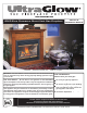
www.regency-fire.com G36D Zero Clearance Direct Vent Gas Fireplace MODELS: G36D-NG1 Natural Gas G36D-LP1 Propane WARNING: If the information in these instructions are not followed exactly, a fire or explosion may result causing property damage, personal injury or loss of life. FOR YOUR SAFETY: Do not store or use gasoline or other flammable vapors and liquids in the vicinity of this or any other appliance.
To the New Owner: Congratulations! You are the owner of a state-of-the-art Gas Fireplace by FIREPLACE PRODUCTS INTERNATIONAL. The G36D is a hand crafted appliance and has been designed to provide you with all the warmth and charm of a wood fireplace at the flick of a switch. The model G36D has been approved by Warnock Hersey for both safety and efficiency. As it also bears our own mark, it promises to provide you with economy, comfort and security for many trouble free years to follow.
TABLE OF CONTENTS SAFETY LABEL OPERATING INSTRUCTIONS Safety Label ..................................................................4 Operating ....................................................................34 Instructions ..................................................................34 Lighting Procedure ......................................................34 Shutdown Procedure ...................................................34 First Fire ..................................................
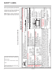
300 This is a copy of the label that accompanies each G36D Zero Clearance Direct Vent Gas Fireplace. We have printed a copy of the contents here for your review. The safety label is located on the front inside base of the unit, visible when the bottom louver is open. NOTE: UltraGlow® units are constantly being improved. Check the label on the unit and if there is a difference, the label on the unit is the correct one.
INSTALLATION IMPORTANT MESSAGE SAVE THESE INSTRUCTIONS The G36D-NG1 or G36D-LP1 Direct Vent Fireplace must be installed in accordance with these instructions. Carefully read all the instructions in this manual first. Consult the "authority having jurisdiction" to determine the need for a permit prior to starting the installation. It is the responsibility of the installer to ensure this fireplace is installed in compliance with manufacturer's instructions and all applicable codes.
INSTALLATION This includes: 1) Clocking the appliance to ensure the correct firing rate (rate noted on label 26,000 Btu/h) after burning appliance for 15 minutes. 5) This appliance is Listed for bedroom installations when used with a Listed Millivolt Thermostat. Some areas may have further requirements, check local codes before installation. 2) If required, adjusting the primary air to ensure that the flame does not carbon. First allow the unit to burn for 15-20 min. to stabilize.
INSTALLATION CLEARANCES The clearances listed below are Minimum distances unless otherwise stated: A major cause of chimney related fires is failure to maintain required clearances (air space) to combustible materials. It is of the greatest importance that this fireplace and vent system be installed only in accordance with these instructions. MANTEL LEG CLEARANCES Combustible mantel leg clearances as per diagram below: 2) Frame in the enclosure for the unit with framing material.
INSTALLATION COMBUSTIBLE MANTELS Because of the extreme heat this fireplace emits, the mantel clearances are critical. Combustible mantel clearances from top of unit are shown in the diagram below. Note: A non-combustible mantel may be installed at a lower height if the framing is made of metal studs covered with a non-combustible board. These drawings are to scale at 1:6 (one inch = 6 inches) Mantel can be installed anywhere in shaded area or higher using the above scale.
INSTALLATION Top Header 32-1/2" 37” 40-1/2" 1/2" Drywall 10" dia. hole through wall for Flex or for DuraVent 3) Attach the standoff securely to the top with 2 screws per standoff (on opposite corners). 2" 3-1/2" 4" Opening for gas connection "C" Screw Position: For a facing material depth of 1-1/4" (32mm), the top facing support must be reversed. 17-1/8" Note: 40-1/2" (1029mm) is the minimum height for both flex termination or Simpson Dura-Vent venting.
V E V M V B Vent terminal . F V V A G B C V A V B B V A K B H j N V Area where terminal is not permited A V 18" L A Note: - A vent shall not terminate directly above a sidewalk or paved driveway which is located between two single family dwellings and serves both dwellings. - Only permitted if veranda, porch, deck, or balcony is fully open on a minimum of two sides beneath the floor. - If the vent termination is accessible, a certified guard shall be installed.
INSTALLATION VENTING UltraGlow® Direct Vent System (Flex) Horizontal Terminations Only These venting systems, in combination with the G36D Direct Vent Gas Fireplace, have been tested and listed as a direct vent heater system by Warnock Hersey. The location of the termination cap must conform to the requirements in the Vent Terminal Locations diagram in the "Exterior Vent Termination Locations" section.
INSTALLATION RIGID PIPE VENTING COMPONENTS LIST All Simpson Dura-Vent components are available directly from FPI.
INSTALLATION RIGID PIPE VENTING SYSTEMS Horizontal or Vertical Terminations The minimum components required for a basic horizontal termination are: 1 1 1 1 1 Flat Wall Installation Horizontal Termination Cap 90o Elbow Rigid Pipe Adaptor Wall Thimble Length of pipe to suit wall thickness (see chart) Wall thickness is measured from the back standoffs to the inside mounting surface of termination cap.
INSTALLATION RIGID PIPE VENTING ARRANGEMENTS - HORIZONTAL TERMINATIONS UltraGlow® DIRECT VENT SYSTEM (FLEX) (Propane & Natural Gas) The diagram shows all allowable combinations of vertical runs with horizontal terminations, using one 90o elbow (two 45o elbows equal one 90o elbow). Note: Must use optional rigid pipe adaptor (Part # 510-994) when using rigid vent systems.
INSTALLATION RIGID PIPE VENTING ARRANGEMENTS - HORIZONTAL TERMINATIONS UltraGlow® DIRECT VENT SYSTEM (FLEX) (Propane & Natural Gas) The diagram below shows examples of horizontal termination arrangements using two 90o elbows (two 45o elbows equal one 90o elbow). Note: 1) 2) 3) 4) A maximum of two 90o elbows are permitted. A minimum of 6 ft. (1.8m) vertical from base of unit is required if two 90o elbows are used. Minimum distance between elbows is 2 ft. (0.6m).
INSTALLATION RIGID PIPE VENTING ARRANGEMENTS - VERTICAL TERMINATIONS (Propane & Natural Gas) The G36D is approved for a maximum 23 ft. (7.0m) vertical, with a maximum 12 ft. (3.7m) horizontal offset using two 90o elbows (two 45o elbows equal one 90o elbow) with Rigid Pipe vent systems for Propane and Natural Gas, as per diagram 1. The G36D is approved for a maximum 37 ft. (11.3m) straight vertical, including a maximum 20" (0.
INSTALLATION The G36D is approved for a maximum 37 ft. (11.3m) straight vertical, with Rigid Pipe vent systems for Propane and Natural Gas, as per the diagram 3. The shaded area in the diagram 3 shows all allowable combinations of straight vertical and offset to vertical terminations with Rigid Pipe vent systems for Propane and Natural Gas. Maximum two 45o elbows allowed. • • • Vent must be supported at offsets Firestops are required at each floor level and whenever passing through a wall.
INSTALLATION VERTICAL TERMINATION WITH CO-LINEAR FLEX SYSTEM THE APPLIANCE MUST NOT BE CONNECTED TO A CHIMNEY FLUE SERVING A SEPARATE SOLID FUEL BURNING APPLIANCE. Masonry chimneys may take various contours which the flexible liner will accommodate. However, keep the flexible liner as straight as possible, avoid unnecessary bending. The Air Intake pipe must be attached to the inlet air collar of the termination cap.
INSTALLATION VENTING ARRANGEMENTS - VERTICAL TERMINATIONS with Co-linear Flex System for both Residential & Manufactured Homes into Masonry Fireplaces The shaded area in the diagrams show the allowable vertical terminations.
INSTALLATION UNIT INSTALLATION WITH HORIZONTAL TERMINATION Install the vent system according to the manufacturer's instructions included with the components. 1) Set the unit in its desired location. Check to determine if wall studs or roof rafters are in the way when the venting system is attached. If this is the case, you may want to adjust the location of the unit. Rough in the gas preferably on the right side of the unit and the electrical (junction block is on the left side) on the left.
INSTALLATION UNIT INSTALLATION WITH VERTICAL TERMINATION Diagram 5 The four wood screws provided should be replaced with appropriate fasteners for stucco, brick, concrete, or other types of sidings. Note: If installing termination on a siding covered wall, a vinyl siding standoff or furring strips must be used to ensure that the termination is not recessed into the siding. 7) Before connecting the horizontal run of vent pipe to the vent termination, slide the Wall Thimble (Part # 942) over the vent pipe.
INSTALLATION steep roof pitches, the vertical height must be increased. A poor draft, or down drafting can result from high wind conditions near big trees or adjoining roof lines, in these cases, increasing the vent height may solve the problem. 7) Ensure vent is vertical and secure the base of the flashing to the roof with roofing rails, slide storm collar over the pipe section and seal with a mastic. 8) Install the vertical termination cap by twistlocking it.
INSTALLATION G36D-NG1 System Data For 0 to 4500 feet altitude Burner Inlet Orifice Sizes: #42 Max. Input Rating Min. Input Rating 26,000 Btu/h 13,100 Btu/h Supply Pressure min.5.0" w.c. Manifold Pressure (High) 3.8"+/- 0.2"w.c. Log Set: Ceramic fibre, 7 per set. Vent System: Simpson Dura-Vent Direct Vent System or UltraGlow® Direct Vent System (Flex) G36D-LP1 System Data For 0 to 4500 feet altitude Burner Inlet Orifice Sizes: #53 Max. Input Rating Min.
INSTALLATION CONVERSION KIT #773-969 FROM NG TO LPG FOR G36D-1MUST USING 820 GAS VALVE THIS CONVERSION BE SIT DONE BYNOVA A QUALIFIED GAS FITTER IF IN DOUBT DO NOT DO THIS CONVERSION !! THIS CONVERSION MUST BE DONE BY A QUALIFIED GAS FITTER IF IN DOUBT DO NOT DO THIS CONVERSION !! 11) Remove the black protection cap by hand from the high-low knob (Fig.1). Each Kit contains one LPG Conversion Kit and one DC Sparker Kit. LPG Conversion Kit Contains: Qty.
INSTALLATION 15) Using the Allen wrench as shown in Fig.4, rotate the screw clockwise until snug, do not overtighten. WARNING! Also check that the pilot and main burner injectors are appropriate for the gas type. 24) Install the 3/4" nylon plug to cover up the hole on the mounting bracket. 18) Reverse steps 5) to 2). 19) Attach the label "This unit has been converted to LPG" near or on top of the serial # decal. 20) Replace yellow "Natural Gas" label with red "Propane" label. Fig.
INSTALLATION 28) Install the 1/2" bushing to the heat shield. 32) Mount the heat shield to the DC Sparker. Secure into place with the velcro, which is provided in the kit. 29) Run the other end of the ground wire and DC spark generator wires through the bushing on the heat shield. Heat Shield 33) Find a location which is not too hot and is easy to reach for changing the battery. Note: It should be kept away from the chain. Chain 30) Plug the DC spark generator wires to the DC Sparker.
INSTALLATION LOG SET INSTALLATION Read the instructions below carefully and refer to the diagrams. If logs are broken do not use the unit until they are replaced. Broken logs can interfere with the pilot operation.
INSTALLATION 6) Position Log 02-54 across the cutouts in Logs 02-51 and 02-53. The notch in the bottom right end fitting against the 5th grate tab. 8) Place Log 02-52 between Logs 02-51 and 02-75 and on the indentation on Log 02-54. The bottom right end sits behind the rear grate tab. 02-75 02-52 02-54 02-51 02-53 02-51 02-54 Log indentation Photo shows rear grate tab. Log 02-51 was removed to show the positioning of Log 02-52.
INSTALLATION 10) Place the embers on the front of the burner tray in the places shown on the photos below. 11) Test fire to ensure proper light off (make sure flame flows smoothly from one end of burner to the other). If there is any flame hesitation, check that area for any blockage of the burner ports. 12) Install flush glass as per instructions in manual. Place embers in these 3 locations on the burner tray.
INSTALLATION STANDARD FLUSH DOOR Use the hook to pull the spring out until you can put the hook into the slot on the bottom door bracket. Repeat for 2nd spring. See diagram 3. The standard flush door comes with a black frame. To install the frame, simply hook the top door flange onto the top of the unit and swing the door towards the unit, diagram 1. Flush Louvers 1) Install each top by clipping the louver lip onto the top louver brackets ensuring that each individual louver is centered from side to side.
INSTALLATION Option 1: REMOTE CONTROL Option 2: WALL SWITCH Option 3: WALL THERMOSTAT Use the UltraGlow® Remote Control Kit approved for this unit. Use of other systems may void your warranty. 1) Run the wire through the right or left side inlet opening. Be careful not to damage wire. A wall thermostat may be installed if desired, connect the wires as per the wiring diagram. Use the table below to determine the maximum wire length.
INSTALLATION WIRING DIAGRAM This heater does not require a 120V A.C. supply for operation. In case of a power failure, the burner switch and the optional remote control/thermostat will continue to operate. (Do not cut the ground terminal off under any circumstances.) Caution: Ensure that the wires do not touch any hot surfaces and are away from sharp edges. CAUTION: Label all wires prior to disconnection when servicing controls.
INSTALLATION INSTALLING THE OPTIONAL FAN 120 Volt AC power is needed for the fan switch and blower. A three wire power cord is provided to be plugged into the receptacle. Note: A 120 Volt AC power cord can be installed at rough-in stage so that the power is available. A three wire power cord can be used. Unit must be grounded at all times. Do not cut the ground terminal off under any circumstances. 5) If the left spring was unhooked in step 3), hook it back into the bracket.
OPERATING INSTRUCTIONS OPERATING INSTRUCTIONS 2) Turn gas control knob so indicator points to "OFF" position and allow 5 minutes for any gas in the combustion chamber to escape. 1) Read and understand these instructions before operating this appliance. 3) Turn gas control knob counterclockwise so indicator points to the "PILOT" position. Depress the gas control knob fully. Depress the igniter button several times until the pilot lights. After approximately one minute, release the gas control knob.
OPERATING INSTRUCTIONS COPY OF THE LIGHTING PLATE INSTRUCTIONS FOR YOUR SAFETY READ BEFORE LIGHTING This appliance must be installed in accordance with local codes, if any; if none, follow the National Fuel Gas Code, ANSI Z223.1/NFP Z223.1/NFPA 54, or Natural Gas and Propane Installation Codes, CSA B149.1. (Australia: AG601, New Zealand: NZS 5261) 5261) W WARNING: If you do not follow these instructions exactly, a fire or explosion may result causing property damage, personal injury or loss of life.
MAINTENANCE 4) Make a periodic check of burner for proper position and condition. Visually check the flame of the burner periodically, making sure the flames are steady; not lifting or floating. If there is a problem, call a qualified service person. 5) The appliance and venting system must be inspected before use, and at least annually, by a qualified field service person, to ensure that the flow of combustion and ventilation air is not obstructed.
MAINTENANCE REMOVING VALVE 11) Remove the 12 Phillips head screws securing the valve tray assembly in place. 1) Shut off the gas supply. INSTALLING VALVE 1) Attach the valve to the valve bracket with the 4 (m5x8 metric) screws provided. 2) Remove louvers. 2) Reconnect the "gas out" flare fitting with an 11/16" wrench. 3) Open and remove the flush door. 4) Remove logs. 3) Reconnect the "gas out" flare nut with a 13/16" wrench. 5) Remove the burner assembly by removing the two Phillips head screws.
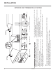
PARTS LIST G36D MAIN ASSEMBLY Part # Description 1) 2) 3) 4) 948-253 510-026 948-045 948-115 Door Handle Hinge Bracket - Left/Right Chain Spring 6) 7) 8) 9) 10) 430-129 910-429 910-428 910-430 904-687 Receptacle Box Mount Box - Receptacle Duplex Receptacle Cover - Receptacle Clamp Connector 20) 510-033 21) 510-064 Top Nailing Strip Side Nailing Strip 23) 780-011 Standoff - Top 24) 780-013 Standoff - Side/Back 27) 28) 29) 30) 34) 35) Part # * * * * * * 910-882 331-917 Description Outer Flue C
PARTS LIST G36D BURNER ASSEMBLY & LOG SET Part # Description 52) 910-190 Piezo Ignitor & Nut 53) 780-021 786-574/P 786-576/P Gasket - Valve Access Plate NG/LP Valve Assy - Natural Gas Valve Assy - Propane 56) * Valve Tray - NG/LP 57) 910-378 910-380 58) * Valve - S.I.T. - Natural Gas Valve - S.I.T. - Propane Valve Bracket 65) * 66) 910-038 910-039 67) * Pilot Bracket Pilot Assy - S.I.T. - 3 Flame NG Pilot Assy - S.I.T.
PARTS LIST G36D FLUSH FRONT ASSEMBLY Part # Description 131) 510-934 510-947 510-932 Flush Glass Trim (Set) - Brass Flush Glass Trim (Set) - Steel Flush Glass Trim (Set) - Gold 132) 904-196 Magnet (1" Round) 133) 780-069 134) 786-520 Flush Louver - Top - Black Assembly - Bottom - Black 135) 940-334/P Glass - Tempered 137) 904-691 139) 936-155 U-Clip Glass Gasket (Tadpole) 140) 948-042 Spring Hinge - Black *Not available as a replacement part.
NOTES ___________________________________________________ ___________________________________________________ ___________________________________________________ ___________________________________________________ ___________________________________________________ ___________________________________________________ ___________________________________________________ ___________________________________________________ ___________________________________________________ ______________________________________
NOTES ___________________________________________________ ___________________________________________________ ___________________________________________________ ___________________________________________________ ___________________________________________________ ___________________________________________________ ___________________________________________________ ___________________________________________________ ___________________________________________________ ______________________________________
WARRANTY UltraGlow® products, are designed with reliability and simplicity in mind. In addition, our internal Quality Assurance Team carefully inspects each unit thoroughly before it leaves our door. UltraGlow® is pleased to extend this one year warranty to the original purchaser of a UltraGlow® product. This warranty is not transferable.
Register your UltraGlow® online at http://www.regency-fire.com Installer: Please complete the following information Dealer Name & Address: ______________________________________________ ___________________________________________________________________ Installer: ___________________________________________________________ Phone #: ___________________________________________________________ Date Installed: ______________________________________________________ Serial No.