
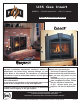
Gas Inserts Owners and Installation Manual

7
U35 FPI Direct Vent Gas Insert
9) Final check: Before leaving this unit with
the customer, the installer must ensure
that the appliance is fi ring correctly. This
includes:
a) Clocking the appliance to ensure the
correct fi ring rate.
b) Adjusting the primary air, if required,
to ensure that the fl ame does not
carbon. Refer to the "Gas Insert
Aeration System" section.
c) Ensuring that the appliance is venting
correctly.
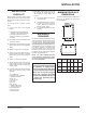
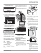
MATERIALS
REQUIRED
No electrical power supply is required for the gas
control to operate. A 120 Volt AC power cord is
hooked up to the fan. Plug the 3 wire cord into
a suitable receptacle. Do not cut the ground
terminal off under any circumstances. When
connected with 120 volts, the appliance must
be electrically grounded in accordance with
local codes, current version of the Canadian
Electrical Code CSA C22.1 (in Canada) or in
the absence of local codes, with the National
Electrical Code ANSI/NFPA 70.
NOTE: This unit is equipped with a heat
sensor thermodisc which will prevent the
blower from operating until the unit reaches
the correct temperature.
INSTALLATION
INSTALLATION
CHECKLIST
Before installing vent system ensure that the
damper plate is open and secure to prevent the
damper plate from falling down and crushing
the liner.
The FPI Gas Insert is installed as listed
below.
1) Locate insert, refer to the following
sections:
a) Installation Into a Solid Fuel Burning
Fireplace or Factory Built Fireplace
b) Minimum Fireplace Dimensions
c) Minimum Clearnces to Combustibles
d) Venting
2) Make the gas connection. Refer to the "Gas
Connection" section.
3) Install the 3" fl ue liner to the sliding connector
plate. Refer to the "Flue Liner Installation"
section.
4) Slide the unit half way into the fi replace.
5) Pull the vent connector plate through the
tapered brackets and fasten to the front
plate. Refer to the "Flue Liner Installation"
section.
6) Slide the unit fully into the fi replace.
7) Test gas pressure. Refer to the "Gas Pipe
Pressure Testing" section. Check aeration
system. Refer to the "Gas Insert Aeration
System" section.
8) Install the standard and optional features.
Refer to the following sections where
applicable:
a. Log Installation
b. Faceplate & Trim Installation
c. Standard Flush Door
d. Flush Trim
e. Flush Louvers
f. Bay Door
g. Bay Trim
h. Bay Louvers
i. Double Screen Doors
j. The Kensington Front
k. Full Screen Doors
l. Remote Control
m. Wall Thermostat.
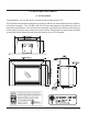
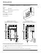
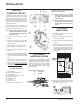
MINIMUM FIREPLACE
DIMENSIONS
The minimum fi replace clearances & dimensions
for the FPI gas fi replace are shown in the
following diagrams:
WARNING:
Electrical Grounding Instructions
This appliance is equipped with
a three pronged (grounding) plug
for your protection against shock
hazard and should be plugged
directly into a properly grounded
three-prong receptacle. Do not cut
or remove the grounding prong
from this plug.
A
B
D
E
C
Max Lentil
Bar Depth
A
Height
B
Depth
C
Width
(rear)
D
Width
(front)
E
Regency
Countour
Faceplate
9" 25" 17" 25" 32-1/4"
Regency
Molded
Faceplate
10" 26-3/4" 18" 25" 34-1/2"
Palace
Front
10" 26-3/4" 18" 25" 34-1/2"