GF55 & GFI55 TECHNICAL MANUAL Freestanding and Fireplace Insert Pellet Stove WARNING: Improper installation, adjustment, alteration, service or maintenance can cause injury, property damage, or loss of life. Refer to this manual. For assistance or additional information consult an authorized installer or service agency. FOR YOUR SAFETY: Do not store or use gasoline or other flammable vapours and liquids in the vicinity of this or any other appliance.
Safety Note: If this stove is not properly installed, a house fire may result. For your safety, follow the installation instructions, contact local building, fire officials, or authority having jurisdiction about restrictions and installation inspection requirements in your area. The authority having jurisdiction should be consulted before installation to determine the need to obtain a permit.
TABLE OF CONTENTS * This manual is designed for the technician in conjunction with the owner’s manual. * SAFETY LABEL Copy of Serial No. Decal ...............................................4 UNIT DIMENSIONS GF55 Freestanding Pellet Stove ...................................5 GFI55 Fireplace Pellet Insert .........................................6 INSTALLATION Important Safety Information .........................................7 Safety Warnings & Recommendations ..........................
Model / Modèle: GF55 (Stove) GFI55 (Insert) ATTENTION: A Floor Protection E B F E D C A B F A E D B 6” (152 mm) 6” (152 mm) 8” (203 mm) 8” (203 mm) 8” (203 mm) 8” (203 mm) Delta, BC, Canada FPI Fireplace Products International Ltd. Certified for use in Canada & USA Certifié pour installation au Canada et aux Etats-Unis. 15956 Combustible floors must be protected by a non-combustible material. - See Owners Manual.
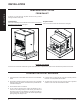
UNIT DIMENSIONS GF55 FREESTANDING PELLET STOVE INSTALLATION 231/16" (586mm) 19/16" (40mm) 197/16" (494mm) 341/8" (866mm) 131/16" (332mm) 247/16" (620mm) 24" (610mm) 5 3/4" (146mm) 20 5/16" (508mm) 14 5/8" (356mm) 129/16" (319mm) 11 7/16" (291mm) 1" (25mm) Greenfire Pellet Stove and Insert Technical Manual 6 11/16" (170mm) 5
UNIT DIMENSIONS INSTALLATION GFI55 FIREPLACE PELLET INSERT 203/8" (517mm) 10" (253mm) 11/16" (26mm) 13" (329mm) 241/16" (610mm) 71/4" (183mm) 303/16" (766mm) 2215/16" (582mm) 225/16" (567mm) 13/8" (35mm) B FACEPLATE DIMENSIONS Regular Faceplate (A) Height 30" (761mm) (B) Width 39-15/16" (1014mm) A Oversize Faceplate 213/16" (538mm) (A) Height 33" (838mm) (B) Width 45-15/16" (1167mm) 2315/16" (609mm) 6 Greenfire Pellet Stove and Insert Technical Manual
INSTALLATION IMPORTANT SAFETY INFORMATION Contact your local building or fire official to obtain a permit and any information on installation restrictions and inspection requirements for your area. To prevent the possibility of a fire, ensure that the appliance is properly installed by adhering to the installation instructions. A Greenfire dealer will be happy to assist you in obtaining information with regards to your local building codes and installation restrictions.
INSTALLATION INSTALLATION REMOVING PELLET STOVE FROM PALLET To remove your new stove from its pallet, remove the two (2) screws securing the bottom to the pallet. Freestanding: One screw can be easily seen from behind but to access the second screw the ashpan must be removed. See figure 1. Fireplace Insert: There is one screw on either side of the bottom. See figure 2. Figure 2: Removing GFI55 From Pallet. Figure 1: Removing GF55 From Pallet.
INSTALLATION GF55 FREESTANDING PELLET STOVE INSTALLATION CLEARANCES TO COMBUSTIBLES ALCOVE CLEARANCES These dimensions are minimum clearances to combustibles, however it is highly recommended that you leave sufficient room on each side (20" where possible) for servicing, routine cleaning and maintenance. Minimum Width 36" (914mm) This pellet stove requires floor protection.
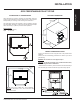
INSTALLATION INSTALLATION VENT TERMINATION REQUIREMENTS Letter Minimum Clearance Description A 24 in (61 cm) B 48 in (122 cm) C 24 in (61 cm) From above any door or window that may be opened. D 24 in (61 cm) To any adjacent building, fences and protruding parts of the structure. E 24 in (61 cm) Below any eave or roof overhang F 12 in (30 cm) To outside corner. G 12 in (30 cm) To inside corner, combustible wall (vertical and horizontal terminations).
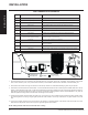
INSTALLATION EXHAUST AND FRESH AIR INTAKE LOCATION OUTSIDE FRESH AIR CONNECTION Base of unit to center of flue 20-5/16" (508mm) Side of unit to center of flue 6-11/16" (170mm) Center of unit to center of flue 5-3/4" (146mm) FRESH AIR INTAKE: Base of unit to center of intake 14-5/8" (356mm) Side of unit to center of intake 11-7/16" (291mm) Center of unit to center of intake A Fresh-air intake is strongly recommended for all installations.
INSTALLATION INSTALLATION HORIZONTAL EXHAUST THROUGH WALL INSTALLATION Vent installation: install vent at clearances specified by the vent manufacturer. A chimney connector shall not pass through an attic or roof space, closet or similar concealed spaces, or a floor, or ceiling. Where passage through a wall or partition of combustible construction is desired, the installation shall conform to CAN/CSA-B365 Installation Code for Solid-Fuel-Burning Appliances and Equipment.
INSTALLATION VERTICAL RISE WITH HORIZONTAL TERMINATION INSTALLATION 1. Choose a stove location that is ideal. Refer to "Locating Your Pellet Appliance" section. 2. Place the unit on the hearth pad (if installed on a carpeted surface) and space the unit in a manner so when the pellet vent is installed vertically, it will be 3” (76 mm) away from a combustible wall. 3. Locate the center of the fresh air intake pipe on the unit.
INSTALLATION HEARTH MOUNT INSTALLATION INSTALLATION OUTSIDE VERTICAL INSTALLATIONS To accomplish a outside vertical pipe installation, follow steps 1 through 5 in the "Inside Vertical Installation" section and then finish it by performing the following (refer to Figure 16). 1. Lock fireplace damper in the open position. 1. Install a tee with clean out on the outside of the house. 3. Connect a clean-out tee or a 90° elbow to the exhaust pipe. 2. Install PL vent upward from the tee.
INSTALLATION GFI55 PELLET INSERT The fireplace insert is certified to be installed into a masonry fireplace only and/or zero clearance wood burning factory built fireplace where allowed by local codes. This model includes a surround faceplate and a pedestal. When installing this unit, ensure that the pedestal is removed from the inside of the hopper and installed on the bottom of the unit.
INSTALLATION EXHAUST AND FRESH AIR INTAKE LOCATION INSTALLATION EXHAUST: Base of unit to center of flue 9-1/16" (229mm) Side of unit to center of flue 6-1/8" (156mm) Center of unit to center of flue 5-3/4" (146mm) FRESH AIR INTAKE: Base of unit to center of intake 3-7/16" (87mm) Side of unit to center of intake 10-7/8" (277mm) Center of unit to center of intake MASONRY FIREPLACE INSERT INSTALLATION The GFI55 requires a surround faceplate and a pedestal.
INSTALLATION When installing the fireplace insert into a zero clearance fireplace, where allowed by local codes, DO NOT cut or modify any factory firebox parts. If the fireplace insert does not fit into a zero clearance fireplace we recommend you use an Greenfire freestanding model and install as a hearth mounted unit. Install a 3” (76 mm) flex pipe from the stove to the top of the chimney. Refer to "Hearth Mount Installation".
INSTALLATION INSTALLATION INSTALLATION AND REMOVAL OF CONTROL PANEL IN THE SURROUND PANEL When installing the circuit board control panel into the surround panel, the surround does not need to be assembled. The circuit board will be found in the firebox. Place the circuit board control panel on the backside of the right surround panel so the hinge is on the outside and the top and bottom holes on the control panel line up with those on the surround.
INSTALLATION PLATED DOOR INSTALLATION TOOLS REQUIRED: a) 11/32" socket REMOVAL OF DOOR COVER: When stove is off and cool, open the door. Remove the four (4) #8 hex nuts around the inside of the glass retainer shown in Figure 37. Remove door cover from door by gently sliding the studs out of the holes. If it is difficult to remove the cover, the glass retainer may be pinching the threads on the studs. Slightly loosen the four (4) screws (by each of the studs). 1.
INSTALLATION INSTALLATION SLIDER / DAMPER SET-UP THE SLIDER / DAMPER MUST BE SET AT TIME OF INSTALLATION, IT IS USED TO REGULATE THE AIRFLOW THROUGH THE PELLET STOVE. A Qualified Service Technician or Installer must set the Slider Damper. The slider damper is used to regulate the airflow through the pellet stove and is located behind the left cab side (refer to Figure 39). The door must be open for the cab side to be removed on all models.
TROUBLESHOOTING TROUBLESHOOTING FAQ'S DO NOT: ● Service the stove with wet hands. The stove is an electrical appliance, which may pose a shock hazard if handled improperly. Only qualified technicians should deal with possible internal electrical failures. ● Do not attempt to remove or loosen any screws from inside the firebox without applying penetrating oil (ie. WD40) to any of the screws. WHAT TO DO IF: TROUBLESHOOTING 1. The stove will not start. 2. The stove will not operate when hot. 3.
TROUBLESHOOTING 9Blocked exhaust / venting system - Have stove and venting cleaned and inspected. 9Severe negative pressure in area where unit is installed - Check the operation by opening a window, does this solve the problem? If it does, install fresh air intake to unit or room. Venting system may require vertical section to move termination into a low pressure zone. 9Vacuum Switch failure - Bypass the vacuum switch, if this corrects the problem check for above problems before replacing the Vacuum Switch.
TROUBLESHOOTING WIRING DIAGRAM Combustion Blower Blue 120 °F Exhaust Temperature Sensor N/O Brown White Vacuum Switch Brown Centre Post Un-used Grey 160 °F Purple TROUBLESHOOTING Convection Temperature Switch N/O Grey Black Red White White White 120 V Grounded Connector Ignitor Ground Green Thermostat White White Yellow Black Auger Motor 5 Amp Fuse Convection Blower Red Black Yellow White Blue Brown Brown Purple Grey Grey Orange Orange Connect Thermostat Here Greenfire Pellet Stove
PARTS LIST PARTS LIST & COMPONENTS Part # 1) 2) 3) 4) GF55-001 GF55-002 GF55-003 GF55-004 Description Auger Motor 115V 1 Rpm Combustion Blower Motor Only 115V Convection Blower 115V Ignitor 300 Watt 115V 5) GF55-005 GF55-006 GF55-007 GF55-008 Circuit Board W/Tstat Switch 115V Circuit Board Fuse (Set 2) Circuit Board Wire Harness Circuit Board Control Panel Decal 6) 7) 8) 9) GF55-009 GF55-010 GF55-011 GF55-012 120 Ceramic Exhaust Temp Sensor 160 Ceramic Convection Fan Sensor 200 High Limit Sensor Manu
PARTS LIST PELLET STOVE COMPONENTS 8 3 5 7 14 6 2 1 9 PARTS LIST Greenfire Pellet Stove and Insert Technical Manual 25
PARTS LIST GF55 FREESTANDING PELLET STOVE 17 25 26 28 19 16 20 12 21 4 11 10 13 15 18 29 34 PARTS LIST 27 26 Greenfire Pellet Stove and Insert Technical Manual
PARTS LIST GFI55 PELLET INSERT 22 32 23 30 31 33 24 PARTS LIST Greenfire Pellet Stove and Insert Technical Manual 27
WARRANTY FPI is the manufacturer of the Greenfire line of heating products. At FPI, our commitment to the highest level of quality and customer service is the most important thing we do. Each Greenfire stove is built on a tradition of using only the finest materials and is backed by our Exclusive Lifetime Limited Warranty to the original purchaser. With Greenfire, you’re not just buying a stove, you’re buying a company with years of unequalled performance and quality.
WARRANTY Exclusions and Limitations: 1. This Warranty does not cover tarnish, discoloration or wear on the plating or paint. 2. This Warranty excludes wear and tear or breakage caused by cleaning, moving or service on log set. 3. A qualified installer must install this stove or fireplace. This Limited Warranty covers defects in materials and workmanship only if the product has been installed in accordance with local building and fire codes; in their absence, refer to the owner’s manual.
WARRANTY 19. The paint on the Metal Brick Liner may peel. This is due to the extreme conditions applied to the paint during normal usage. It is not a flaw and is not covered under warranty. 20. FPI is free of liability for any damages caused by the fireplace or stove, as well as inconvenience expenses and materials. The Limited Warranty does not cover incidental or consequential damages. 21.
NOTES ___________________________________________________ ___________________________________________________ ___________________________________________________ ___________________________________________________ ___________________________________________________ ___________________________________________________ ___________________________________________________ ___________________________________________________ ___________________________________________________ ______________________________________
FPI fireplaces are designed with reliability and simplicity in mind. In addition, our internal Quality Assurance Team carefully inspects each unit thoroughly before it leaves our door. FPI Fireplace Products International Ltd. is pleased to extend this Limited Lifetime Warranty to the original purchaser of a FPI Product.