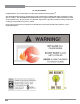
U32SE Sunrise Gas Insert Owners & Installation Manual MODELS: U32SE-NG5 U32SE-LP5 www.regency-fire.com WARNING: FOR YOUR SAFETY Improper installation, adjustment, alteration, service or What to do if you smell gas: maintenance can cause injury or property damage. Refer to Do not try to light any appliance this manual. For assistance or additional information consult Do not touch any electrical switch: an authorized installer, service agency or the gas supplier. do not use any phone in your building.
TO THE NEW OWNER Congratulations! You are the owner of a state-of-the-art Gas Insert by Regency®. The U32SE Gas Insert has been designed to provide you with all the warmth and charm of a fireplace, at the flick of a switch. The U32SE-NG5 and U32SE-LP5 have been approved by Warnock Hersey/Intertek for both safety and efficiency. As it also bears our own mark, it promises to provide you with economy, comfort and security for many trouble free years to follow.
INFORMATION FOR MOBILE/MANUFACTURED HOMES AFTER FIRST SALE This FPI product has been tested and listed by Warnock Hersey as a Direct Vent Wall Furnace to the following standards: CAN/ CGA-2.17-M91, and ANSI Z21.88-2009/CSA 2.33-2009.
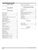
TABLE OF CONTENTS Copy of safety decal .....................................................5 Optional Hearth Trim Installation .................................28 Low Profile faceplate installation .................................29 Low profile - Optional Hearth Trim Installation.............31 REQUIREMENTS OPERATING INSTRUCTIONS MA Code - CO Detector.................................................6 Operating Instructions ................................................32 Lighting Procedure ........
SAFETY LABEL This is a copy of the label that accompanies each U32SE-5 Gas Insert. We have printed a copy of the contents here for your review. The safety label is located on a plate inside the base of the unit visible when the bottom louver is opened. NOTE: Regency®units are constantly being improved. Check the label on the unit and if there is a difference, the label on the unit is the correct one.
REQUIREMENTS MA Code - CO Detector (for the State of Massachusetts only) 5.08: Modifications to NFPA-54, Chapter 10 (2) Revise 10.8.
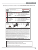
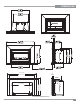
DIMENSIONS 40-3/4” (1036mm) 7/8” (22mm) 35-15/16” (912mm) 23-15/16” (607mm) 14-5/8” (371mm) 27-7/8” (708mm) 21-15/32” (545mm) 9-15/16” (252mm) Low Profile Faceplate Dimensions U32SE-5 FPI Direct Vent Gas Insert 7
INSTALLATION IMPORTANT MESSAGE SAVE THESE INSTRUCTIONS The FPI Gas Insert must be installed in accordance with these instructions. Carefully read all the instructions in this manual first. Consult the building authority having jurisdiction to determine the need for a permit prior to starting the installation. NOTE: Failure to follow the instructions could cause a malfunction of the heater which could result in death, serious bodily injury, and/or property damage.
INSTALLATION SPECIFICATIONS At pressures over 1/2 psig, the pipe to the unit must be disconnected. Gas Input Capacity: Natural Gas 24,500 Propane 20,500 Min. Input Natural Gas Propane 16,500 17,000 Btu/h Btu/h Btu/h Btu/h Fuels: Approved for use with both natural gas, and propane. Approved as is for use at 0' to 4,500' (0-1370m). Electrical: 120V A.C. system. Circulation Fan: Variable speed, 110 CFM. Vent System: 3" co-linear aluminum flex.
INSTALLATION INSTALLATION CHECKLIST MANUFACTURED MOBILE HOME ADDITIONAL REQUIREMENTS Before installing vent system ensure that the damper plate is open and secure to prevent the damper plate from falling down and crushing the liner. The FPI Gas Insert is installed as listed. 1) Check all clearances to combustibles, (Refer to sections "Minimum Fireplace Dimensions and Clearances to Combustibles) 2) Make the gas connection.
INSTALLATION COMBUSTIBLE MANTEL CLEARANCES G 10 8 6 4 2 0 12 18 3-1/2" Mantel 14 GAS CONNECTION WARNING: Only persons licensed to work with gas piping may make the necessary gas connections to this appliance. 1) If the appliance is to be installed into an existing chimney system, thoroughly clean the masonry or factory built fireplace. 12" Mantel 16 47” (1194mm) to ceiling GAS CONNECTION 12 2) The appliance is provided with an opening on the left hand side of the control compartment.
INSTALLATION FLUE LINER INSTALLATION 6) When finished reading manometer, turn off the gas valve, disconnect the hose and tighten the screw (clockwise) with a 1/8" flat screwdriver. Note: Screw should be snug, but do not over tighten. 1) Cut the flex liner as required. 2) Mark the end of one liner to indicate Inlet. GAS INSERT AERATION SYSTEM 3) Connect the other end of the above liner to the inlet side of the termination adaptor, seal connection with high temperature silicone. Secure with gear clamp.
INSTALLATION CONVERSION KIT # 425-972 FROM NG TO LP U32SE-5 using SIT 886 NOVA Gas Valve THIS CONVERSION MUST BE DONE BY A QUALIFIED GAS FITTER IF IN DOUBT DO NOT DO THIS CONVERSION!! Each Kit contains one LPG Conversion Kit LPG Conversion Kit Contains: Qty. Part # Description 1 1 904-163 918-590 1 1 1 908-528 904-529 910-101 1 1 911-009 918-856 For the U32SE only: 3) Remove the burner by undoing the 2 screws as shown below.
INSTALLATION 18) Reinstall new burner orifice LPG stamped #54 or LPG Orifice #56 for use with Faceplate (orifice supplied with faceplate) and tighten. For both U32SE & P33E-4 units: 19) Remove regulator and discard. Install the Hi/Lo pressure regulator onto the valve with 2 screws as shown below. Pilot Cap 9) Pull off the pilot cap to expose the pilot orifice. 15) Undo clip and remove pilot cap to expose pilot orifice.
INSTALLATION OPTIONAL WALL THERMOSTAT OPTIONAL REMOTE CONTROL A wall thermostat may be installed if desired, follow the wiring diagram below. FPI offers an optional programmable thermostat but any 250-750 millivolt rated non-anticipator type thermostat that is CSA, ULC or UL approved may be used. Use the FPI Remote Control Kit approved for this unit. Use of other systems may void your warranty. CAUTION Do not connect the millivolt wall thermostat wires to the 120V wires.
INSTALLATION WIRING DIAGRAMS This heater does not require a 120V A.C. supply for operation. In case of a power failure, the burner switch and the optional remote control/ thermostat will continue to operate. However, a 120V A.C. power supply is needed for the fan/blower operation. Caution: Ensure that the wires do not touch any hot surfaces and are away from sharp edges. SureFire™ Switch 0.886.
INSTALLATION AC POWER ADAPTOR INSTALLATION (FOR SUREFIRE SYSTEMS) An optional AC power adaptor may be installed as a constant power source for the SureFire system. IMPORTANT: Recommend removing the 4-AA batteries in the SureFire receiver. This will avoid battery leakage and power drainage. 4-AA Battery pack may be re-installed into receiver during power outages. NOTE: For all Gas Fireplaces 120 volt power must be brought to the receptacle box inside the ERWWRP RI WKH ¿UHER[ (provided with the unit).
INSTALLATION GT REMOTE INSTALLATION 1) Shut off the gas supply and disconnect all power to the unit. 8) Plug in receiver DC supply wire to the DFC supply- as shown below. 2) Remove the louvers, bay door or faceplate if installed. 3) Disconnect battery pack - located on the floor of the unit, as shown below and discard. Do not use battery pack with receiver. 9) Install 4 - AA batteries into the receiver, ensure correct polarity. 4) Remove DFC (digital firebox control box) from the floor of the unit.
INSTALLATION GTM REMOTE INSTALLATION 1) Shut off the gas supply and disconnect all power to the unit. 2) Remove the louvers, bay door or faceplate, if installed. 3) Disconnect battery pack - located on the floor of the unit, as shown below. Do not use battery pack with receiver. 4) Remove DFC (digital firebox control box) from the floor of the unit. 6) Locate green and white ON/OFF wires. Connect the TPTH and TH wires - green to green and white to white as shown below.
INSTALLATION 10) Install 4 - AA batteries into the receiver. Ensure correct polarity. 13) Reinstall the DFC box onto the velcro pad on the floor of the unit. 14) Install the heat shield to the receiver with two screws and attach to the floor of the unit with a velcro pad. Heat shield 11) Plug receiver wire harness into the back of the receiver and bundle wires with the wire clip - as shown below. 15) Reverse steps 5 and 4. 16) Match the remote control to the receiver - see remote control instructions.
INSTALLATION GLASS CRYSTAL OR OPTIONAL CERAMIC STONES INSTALLATION ON BURNER Evenly spread the Glass Crystals or optional Ceramic Spa Stones or Volcanic Stones over the burner. Ensure the crystals (or stones) do not overlap too much as this will effect the flame pattern. IMPORTANT NOTE: Only the supplied approved Glass Crystals and Ceramic Spa / Lava Stones are to be used with these fireplaces.
INSTALLATION OPTIONAL PEBBLE / CRYSTAL INSTALLATION FOR FIREBOX BASE Firebox (Around Burner) Packages Unit Glass Crystals Pebbles HZ54E / HZ54EPV 6 lbs 2 packages (6 x bags pebbles) HZ42 / HZ42E / HZ40E 5 lbs 2 packages (6 x bags pebbles) HZ42ST / HZ42STE / HZ42STEPV 5 lbs 2 package (6 x bags pebbles) HZ30E 2 lbs 1 package (3 x bags pebbles) HZI540EB 4 lbs 1.
INSTALLATION OPTIONAL REFLECTIVE PANEL INSTALLATION Before installation, panels must be handled and cleaned as per instructions noted below: Stainless Steel Panels • Stainless panels must be inspected for scratches and dimples prior to installation. All claims to be recorded at this time. Claims for damage after installation will not receive consideration. Black Enamel Panels • Black Enamel panels must be inspected for scratches and dimples prior to installation. All claims to be recorded at this time.
INSTALLATION 6) Remove left and right side panels by removing the clip that holds the panels in place. Right side panel clip shown. 8) Install the back panel by carefully placing it against the back wall of the firebox. Clip Installation of Black Enamel or Stainless Steel Panels 7) Slide the right side stainless steel / black enamel panel in place and secure with the panel clip and screw to the top of the firebox as shown below. Repeat for left side. Back Panel 9) Re-install firebox base.
INSTALLATION STANDARD FLUSH DOOR The standard flush door comes with a black frame. To install the frame, simply hook the top door flange onto the top of the unit and swing the door towards the unit, diagram 1. Be careful that the glass gasket does not roll up; there must be a gap between the gasket and the door lip to ensure that the door sits securely on the unit. Diagram 2. To remove the flush door, reverse the above steps. IMPORTANT NOTE: The chain must rest on TOP of the gas inlet pipe never under it.
INSTALLATION FACEPLATE AND DOOR FRAME INSTALLATION Kit# 425-914 Contents List: 1 1 1 2 2 4 1 1 1) Note: Ensure that the flanges on the sides of the firebox are on the outside, when installing the faceplate (see below).
INSTALLATION 7) Install the door frame by hooking the top flange over the top of the glass door. 8) Lower the door frame gently into place. 9) Run supplied 120V power cord along front face of masonry fireplace and plug into nearest receptacle. 10) Slide unit into final position.
INSTALLATION OPTIONAL HEARTH TRIM INSTALLATION The Hearth Trim is an option that can be used to finish off the installation when the bottom of the fireplace is higher than the hearth or to raise the fireplace. The faceplate is assembled first and then the hearth trim is attached to the faceplate. There are 2 Hearth Trim options; a 2" and a 4".
INSTALLATION LOW PROFILE FACEPLATE INSTALLATION 1) Attach the inner faceplate panel to the insert body using 4 screws in the locations shown below. 4) Tuck the wires into the clip to keep them away from the insert using the clip provided. Attach the clip to the rear of the faceplate to ensure that the wires do not touch the side of the unit. The power cord should be run behind the inner faceplate panel.
INSTALLATION 8) Attach the bottom louver to the 2 hinges using 2 screws per hinge. 10) Take the outer faceplate, line up the openings on the left and right legs and install onto the inner faceplate panel pins. Diagram 7 9) Install the top door pressure retainer, required.
INSTALLATION LOW PROFILE - OPTIONAL HEARTH TRIM INSTALLATION Hearth Trim is an option that can be used to finish off the installation when the bottom of the fireplace is higher than the hearth or to raise the fireplace. 1) For units L390E/HZI390E/L540E/HZI540E–remove 4 screws in locations shown below to remove outer faceplate. ** If no screw holes are present. 3) Remove backing plate by removing 4 screws–lay down flat.
OPERATING INSTRUCTIONS OPERATING INSTRUCTIONS LIGHTING PROCEDURE Before operating this appliance, proceed through the following check list. IMPORTANT To ignite or reignite the pilot, you must first remove the glass door. 1) Read and understand these Instructions before operating this appliance. 2) Check to see that all wiring is correct and enclosed to prevent possible shock. 3) Check to ensure there are no gas leaks. 4) Make sure the glass door is in place.
OPERATING INSTRUCTIONS AUTOMATIC CONVECTION FAN OPERATION The fan operates automatically, turn the knob on the side of the faceplate to adjust to the desired speed. The fan will turn on as the insert comes up to operating temperature. After the unit has been turned off and the unit cooled to below a useful heat output range the fan will shut off automatically. NORMAL OPERATING SOUNDS OF GAS APPLIANCES It is possible that you will hear some sounds from your gas appliance.
OPERATING INSTRUCTIONS COPY OF LIGHTING INSTRUCTION PLATE FOR YOUR SAFETY READ BEFORE LIGHTING This appliance must be installed in accordance with local codes, if any; if none, follow the National Fuel Gas Code, ANSI Z223.1/NFPA 54, or Natural Gas and Propane Installation Codes, CSA B149.1. WARNING: If you do not follow these instructions exactly, a fire or explosion may result causing property damage, personal injury or loss of life.
MAINTENANCE PILOT ADJUSTMENT Periodically check the pilot flames. Correct flame pattern has two strong blue flames: 1 flowing around the flame sensor and 1 flowing across the burner (it does not have to be touching the burner). Burner Flame Sensor GENERAL VENT MAINTENANCE Conduct an inspection of the venting system semiannually. Recommended areas to inspect as follows: 1) Check the Venting System for corrosion in areas that are exposed to the elements.
MAINTENANCE FAN MAINTENANCE If your fan requires maintenance or replacement, access to the fan is through the plate on the rear wall of the firebox. NOTE: the unit MUST NOT be operated without the fan access panel securely in place. Caution: Label all wires prior to disconnecting when servicing controls. Wiring errors can cause improper and dangerous operation. Verify proper operation after servicing. 5) Remove the glass door. a) Remove the 2 hooks shown below at the bottom of the glass door.
MAINTENANCE 8) Remove the base cover by lifting up from the back and manoeuvre out. 13) Remove the fan access plate by undoing the 10 screws shown. Base Cover 9) Remove the back panel by manoeuvring it up and out of the firebox. as shown below. Fan access plate 14) Remove the 3 screws securing the burner bracket as shown below. 10) Remove 1 screw holding the clip securing the right side panel. 11) Remove the side panel. 12) Repeat above 2 steps to remove the left side panel.
MAINTENANCE 16) Remove the burner bracket. 19) Lift Fan Assembly off of the 2 pins, tip foreward and pull through firebox opening. 20) Disconnect green ground wire from power cord. 17) Remove the Fan Air Duct by removing the 2 screws, squeeze the sides together to remove. REPLACING THE FAN 18) Unplug the 2 wires from the fan motor from inside the stove (located on the left side of the motor).
MAINTENANCE VALVE ASSEMBLY REPLACEMENT 1) Turn the unit off and allow it to cool down to room temperature. 2) Turn off the gas supply to the insert. 3) Open the bottom louver. 4) Remove the door frame by lifting out from the bottom and lift up off the glass door. Burner 8) Remove the base cover by lifting up from the back and maneover out. Door Frame Glass Door 5) Remove the glass door. a) Remove the 2 hooks shown below at the bottom of the glass door.
MAINTENANCE 10) Remove the valve tray by undoing the 12 screws as shown below. 11) Slightly lift out valve tray. 12) Disconnect the inlet gas line. 13) Replace valve assembly and gasket, then reverse steps to reinstall new valve assembly.
PARTS LIST MAIN ASSEMBLY Part # Description 1) 420-122 Fan Access Panel 2) 420-142 Gasket - Fan Access Panel 422-518/P Fan Assembly: 3) 910-215/P Fan Motor (120 V) 5) 910-750 Power Cord (120 V) 910-752 Wire Harness (intermediate) 7) 910-142 Thermodisc-Fan Auto ON/OFF 8) * Fan Switch Cover 9) * Thermodisc Bracket 10) 420-140 Flue Restrictor 12) 425-017 Left/Right Panels 425-015 Rear Panel 13) * Levelling Bolt 5/16 x 3" Hex Hd 14) 948-045 Jack Chain 15) 948-247 Spring Lever Handle 16) 948-025 Door Extension S
PARTS LIST BURNER ASSEMBLY Part # Description 9) 1) 2) 3) 4) 5) 6) 7) 8) 911-004 911-005 904-430 904-163 425-010 434-031 425-007 425-574E/P 425-576E/P 425-008 420-201 420-202 Valve - SIT NG Valve - SIT LP Burner Orifice Nat.
PARTS LIST FACEPLATE AND DOOR FRAME 1) 2) 3) 4) Part 425-512 425-513 425-514 425-942 Description Door Bottom Assembly Frame Inside Faceplate Outside Hearth Trim 3 2 1 4 U32SE-5 FPI Direct Vent Gas Insert 43
PARTS LIST LOW PROFILE FACEPLATE Part # 1) 2) 3) 4) 5) * * * * * Description Backplate Assembly Bottom Louver Right mounting bracket Left mounting bracket Front Frame 5 4 1 2 3 44 U32SE-5 FPI Direct Vent Gas Insert
NOTES U32SE-5 FPI Direct Vent Gas Insert 45
NOTES 46 U32SE-5 FPI Direct Vent Gas Insert
WARRANTY Regency® Fireplace Products are designed with reliability and simplicity in mind. In addition, our internal Quality Assurance Team carefully inspects each unit thoroughly before it leaves our facility. FPI Fireplace Products International Ltd. is pleased to extend this limited lifetime warranty to the original purchaser of a Regency® Product. This warranty is not transferable.
Register your Regency® warranty online www.regency-fire.com Reasons to register your product online today! • View and modify a list of all your registered products. • Request automatic email notification of new product updates. • Stay informed about the current promotions, events, and special offers on related products.