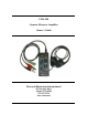
CMA-100 Counter Measures Amplifier Owner’s Guide Research Electronics International 455 Security Place Algood, TN 38506 931-537-3359 www.reiusa.
INTRODUCTION: REI Thank you for purchasing the CMA-100 Countermeasures Amplifier. When doing a Counter-surveillance investigation, it is important to analyze all of the wiring in the environment to ensure that building wiring is not being utilized to transport audio or video information.
PRECAUTIONS: REI 1. Although the maximum input voltage rating indicates that connection to power lines would not be detrimental to the equipment or user, it is NOT recommend maintaining connection to such circuits. Extreme care should be taken when connecting the CMA-100 to an unknown electrical source. Always check line voltage with a multimeter first to determine the risk. 2. Although the maximum input voltage is 250 volts, the meter will only be able to read 199.9 volts.
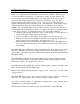
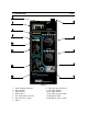
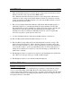
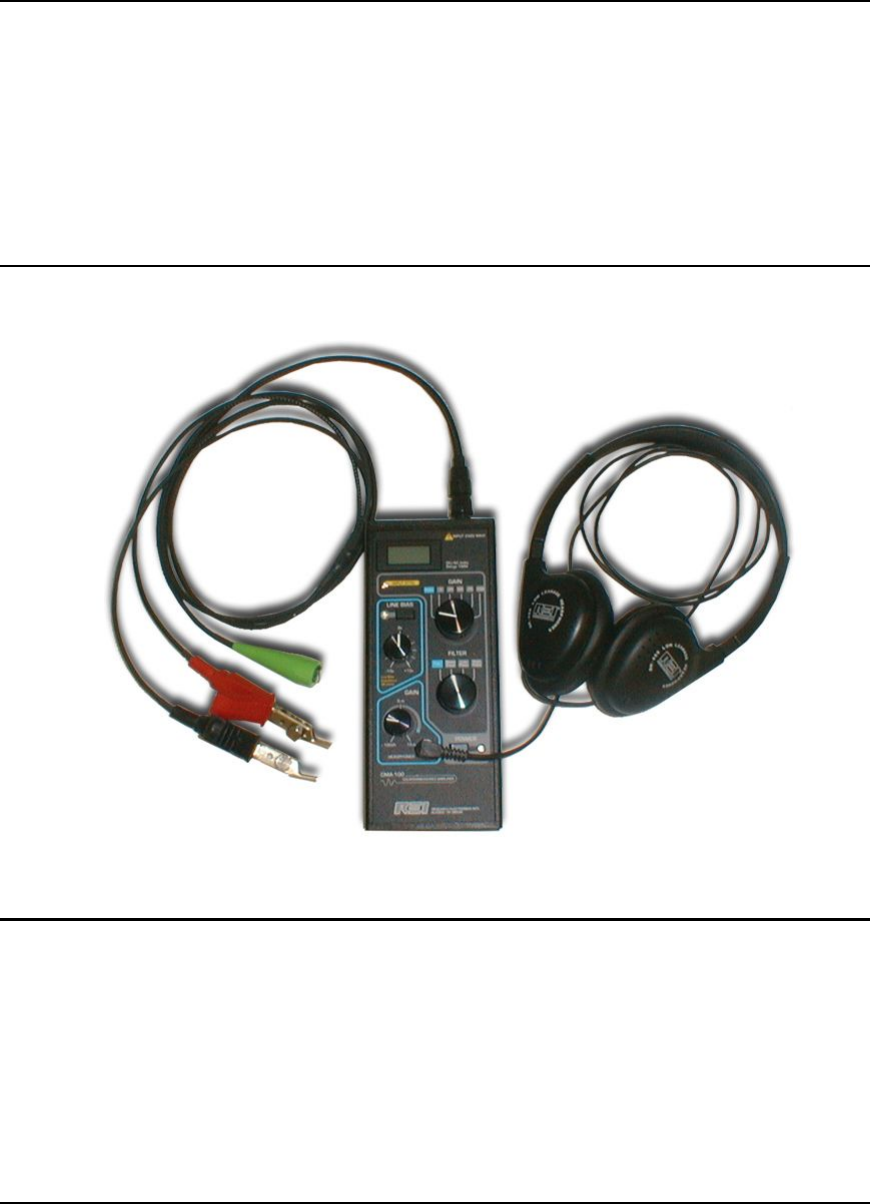
CONTROLS: REI Figure 1 1. 2. 3. 4. 5. 6. 7. On/Low Battery Indicator Power Switch Filter Selector Gain Selector Test Lead Cable Connector Line Out Jack - 3.5mm Meter 8. Input Attenuator Indicator 9. Line Bias Indicator 10. Line Bias Switch 11. Line Bias Voltage Adjust 12. Headphone Gain 13. Headphone Jack - 3.
CONTROLS: REI IDENTIFICATION Please refer to Figure 1 for the following function descriptions. 1. The Power On Indicator is used to identify when the unit is turned on. If the battery voltage falls below 6.9V, then the LED will extinguish and the battery should be replaced. 2. The Power Switch turns the unit on and off. 3. The Filter Selector is a 4 position rotary switch, provides different options of filtering the input audio signal. A.
CONTROLS: REI 7. When the Line Bias Generator is turned off, the voltage meter can measure both AC and DC volts (Note: AC volts are read as RMS values). Note: When the Line Bias Generator is turned on, the voltage meter will measure a combination of the voltage in the circuit that the test leads are connected to and the voltage presented from the Bias Generator. To read only the Bias Generator, remove the Test Leads from any circuit. 8.
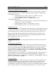
USING THE CMA: REI Single Line and Balanced Line Connections The CMA provides for connections to either single line systems (typically a single line with a ground such as coax) or a balanced pair line such as telephone or LAN wiring. For Single Line systems: • Connect the Green grounding connector to the Black connector. • Connect the Black connector to wiring ground. • Connect the Red connector to the single line to be tested.
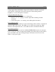
USING THE CMA: REI voltage supply. Then, the DC Bias voltage can be switched on and the control knob slowly turned to both negative and positive directions while listening with the headphones to see if a microphone is activated. Using the CMA with other probes The CMA can be connected to a variety of other probes. • Inductive coil - for coupling to an audio signal without making a metallic connection. • Contact microphone - for detecting sound within physical structures.
SPECIFICATIONS REI INPUT IMPEDANCE: 50k ohm balanced COMMON MODE REJECTION: >75 dB MAXIMUM USABLE INPUT: 31 Vp-p PREAMP AUTO ATTENUATOR: 0 to –40 dB (with Input Atten LED) DYNAMIC RANGE: 145 dB min. MANUAL GAIN CONTROL: 0,25,50,75,100 dB HEADPHONE GAIN CONTROL: 0 to 15 dB MAXIMUM SYSTEM GAIN: 115 dB FREQUENCY RESPONSE: 25 Hz to 44 kHz HIGH PASS FILTER: 320 Hz to 44 kHz LOW PASS FILTER: 25 Hz to 3.2 kHz BAND PASS FILTER: 320 Hz to 3.