
user manual


Version 4 27 Feb 08
Using the MTU-2100 Microwave Test Unit
The MTU-2100 is designed to provide a simple test to verify that the MDC is working
properly. When the button is pressed on the MTU, low power signals are generated at
about 5.9, 11.8, and 17.7GHz for 3 minutes. Each transmitted signal contains a
modulated tone between 900Hz and 1KHz to verify that the signal is radiating from the
MTU-2100. It is important to note that the frequency transmissions from the MTU may
drift slightly. It should also be noted that the MTU test transmitter and the MDC down-
converter both have polarized antennas. When using the MDC in a room environment,
the polarization is often not of great concern because of the depolarizing effect that occurs
from reflections from the room structure. However, when verifying proper operation of the
MDC using the MTU at a close proximity, the polarization of the antennas is important. To
achieve the proper polarization with the high gain antennas of the MDC, the following
positioning should be utilized.
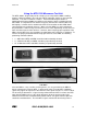
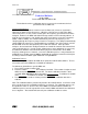
• 3 – 9GHz band: MTU and MDC should be both horizontally oriented.
• 9 – 15GHz band: MTU and MDC should be perpendicularly oriented.
• 15 –21GHz band: MTU and MDC should be perpendicularly oriented.
Figure 12: PROPER MTU ORIENTATION FOR TESTING BAND 1 (3- 9GHZ) OR MDC- 900
Figure 13: PROPER MTU ORIENTATION FOR TESTING BAND 2&3 (9- 21GHZ) FOR MDC-
2100 ONLY
Since the MDC is a very sensitive receiving device, it is very possible for the MDC to
detect sub-harmonics from the MTU. In other words, when using the MTU, additional
signals may appear at frequencies other than the main signals of 5.9, 11.8, and 17.7 GHz.
The best way to determine if a signal is being radiated from the MTU is to move the MTU
away from the MDC and see if the signal disappears or go the analyze mode in the
OSCOR and listen for the modulated tone from the MTU. All signals from the MTU will
contain the modulated tone. The main MTU signals should all be found using Filter A.
REI MDC-2100/MDC-900 14