MSK-1541S Industrial Sewing Machine Instruction Manual
CONTENT Operation Instruction 1. Brief introduction.................................................................................1 2. Main specifications..............................................................................1 3. Installation...........................................................................................1 4. Installing the oil box............................................................................2 5. Adjusting the tension of the belt.............................
1. Brief introduction This machine adpots specific mechanism and timing feed, which can ensure smooth feeding, low noise, and beautiful stitches in apperance. It is constructed with slide link thread take-up, horizontal large rotating hook crochet,synchronic driving. This machien is widely used in the factory of suitcase, sofa, tarpaulins, tents, bag, etc. 2. Mian specifications Heavy duty Application 2500 spm Max.sewing speed Max.
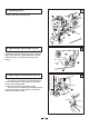
2 4. Installing the oil box (Fig2) 1.Install the bolt 1, oil seal 2 and spacer 3 onto the oil reservoir, and then put the cushion 5 and spacer 8 into the set screw 4, then set it by nut 6. 2.Tighten the oil pot 7 onto the bolt 1. Oil reservoir 3 5. Adjusting the tension of the belt (Fig.3) When adjusting the tension of the belt, please move the height of the motor, and press down the middle of the blet with the force of 9.8N. Then there will be a slack of 15mm. Flywheel Motor wheel belt 4 6.
7. Lubrication (Fig.5) 1.Face plate lubrication a.Loosen the face plate screw; b.Open the face plate 1 in the direction of the arrow; c.Lubricate the place as the arrow shows every day; d.Close the face plate; e.Tighten the screw. 2.Machine body lubrication a.Lubricate the place as the arrows indicate every day; b.When run the machine for the first time or run it again after a long period of non-use, please oil the place as the arrows indicate.
7 9. Threading the bobbin thread (Fig.7) 1.Insert the bobbin into the hook body, pass the thread through the thread hole 1, then pass down throgh the thread tension spring 2. 2.Draw the thread downward, then the bobbin will turn in the direction as the figure shows. 8 10. Installing the rotating hook body (Fig.8) 1.When taking out the rotating hook body, open the gib 1 and pull it off. 2.Align the rotating hook body with the rotating hook shaft and then insert it.
11 13. Threading (Fig11) Thread in the order as shown in Fig. 12 14. Adjusting the stitch length (Fig.12) Turn the stitch length dial plate 1 leftward and rightward to make the marker align with the required figure. Press down the reverse feed lever 2 to start backward sewing, and release it to start normal sewing. 13 15. Adjusting the thread tension (Fig.13) 1.
14 16. Adjusting the thread take-up spring (Fig.14) Small Big 15 1.Changing the swing range of the thread take-up spring a.Loosen the set screw 2, move the stopper 3 leftward and rightward, then adjust the thread take-up spring 1. b.Move the stopper rightward to increase the swing range of the thread take-up spring; on the contrary, to reduce the swing range of the thread take-up spring. 2.
18 20. Adjusting the alternating amount of presser foot (Fig.18) When the presser foot is alternating increasingly, adjust it upward in the range of the long hole of the top feed crank; when the presser foot is alternating decreasingly, adjust it downward, then tighten the nut 2. When the lifting amount of the presser and walking presser foot is different, first align the bottom of the presser foot and walking presser foot with the surface of the needle plate, then loosen the set screw 1.
1.
1. Arm and bed NO.
2.
2.Upper shaft and thread take-up mechanism NO.
3.
3.Needle bar vibrating parts NO. Part Number Name Needle bar Needle bar thread guide Needle Screw Needle bar adapter Oil wick Screw Vibrating shaft Crank Crank pin Screw Oil felt Spring Slide block Vibrating shaft front bushing Vibrating shaft rear bushing Oil felt Needle bar vibrating bracket Oil felt Hinge shaft Screw Position plate (1) Screw Position plate (2) Screw Driven crank Screw Oil felt Wire Guide rail Screw Qt.
4.
4.Upper feed parts NO.
5.
5.Feed parts NO.
6.
6.Lower shaft and rotating hook shaft NO.
7.
7.Thread tension and winding parts NO. Part Number Name Thread tension plate assembly Thread guide plate Screw Thread releasing bar Thread releasing bar bushing Thread tension disc assembly Screw Winder assembly Washer Screw Friction wheel Screw Trimming blade Screw Qt.
8.
8.Knee control parts NO. Part Number Name Knee control lever support Screw Knee control lever Screw Knee control connecting rod Screw Screw Crank Screw Knee control revolving shaft Spring Position block Screw Screw Nut Screw Knee control bell bent bar Bell bracket Screw Knee control bell Cushion Screw Bell bent bar adapter Knee control connecting bar Screw Connecting bushing Spring Screw Qt.
9.
9.Lubrication NO. Part Number Name Oil felt Oil felt support Screw Small oil felt Wire Oil wick Presser plate Thread Hook Screw Oil pot Oil pot cover Screw Oil felt Oil tube Oil wick Oil felt 1 Oil felt 2 Oil retaining plate Screw Oilk felt Oil wick Oil retaining plate Screw Oil wick Oil felt assembly Qt.
10.
10.Accessories NO. Part Number Name Safety guard 1 Safety guard 2 Screw Screw 1 Screw 2 Column Screw V-belt Spool stand Small oil pot Parts bag Spanner Spanner Bobbin Needle Screwdriver (medium) Screwdriver (small) Double ended spanner Screwdriver (big) Machine head cover Oil reservoir Screw Oil pot Adapter Seal ring Presser plate Connecting screw Spacer Seal spacer Connecting nut Connecting hook assembly Rubber cushion Rubber cushion Oil felt Screw Qt.
Reliable Corporation 5-100 Wingold Ave. Toronto, ON M6B 4K7 Canada P 416 785 0200 F 416 785 7038 TF 800 268 1649 www.reliablecorporation.