INSTALLATION AND OPERATING INSTRUCTIONS MANUAL TRANSFER SWITCHES FROM 0
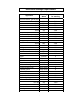
Residential Wattage Requirements Running Watts Add watts for starting 300 500 500 600 700 875 500 750 750 1000 1400 2100 750 1000 1400 2350 800 1050 800 1300 2150 2300 550 750 on bulb 50-200 100-300 600-1500 1750 1050-1850 1100-1500 650-800 400 1150 700 1100 1400 0 0 0 0 0 0 0 0 0 2300 1800 700 1450 800-1100 300-1500 1200 1400 1400 0 0 0 Appliance Furnace blower, gas or fuel 1/8 hp 1/8 hp 1/6 hp 1/4 hp 1/3 hp 1/2 hp Shallow well pump 1/3 hp 1/2 hp Sump pump 1/3 hp 1/2 hp Refrigerator or freezer
Warnings • Cautions Warning: When using this product with a portable generator, do not operate the generator indoors or in an enclosed area. Do not operate a generator where the exhaust fumes can accumulate indoors or in an enclosed area like a garage or close to windows or doors. Warning: Improper installation of this transfer switch could cause damage or personal injury by electrocution or fire.
Reliance Installation and Operating Instructions Key Components of the Reliance Transfer Switch Circuit breakers Handle tie Circuit selector switches Watt meters (select models only) Wiring Compartment Cover Power Inlet (not installed on indoor models). Figure 1 Circuit breakers. Each transfer switch circuit has a 15- or 20-amp push-to-reset circuit breaker that protects the branch circuit when the circuit selector is in the GEN position.
Installation Instructions Preparing for Installation You will need the following items: Electric drill Screwdriver Wire cutters/stripper Hammer Four anchors and screws 4, 6, 8 or 10 yellow wire connectors (depending on the model) 4 red wire connectors for the 20A and 30A hard-wire models 4 blue wire connectors for the 50A hard-wire models The following five steps generally apply to all transfer switch installations.
Wiring the Reliance Transfer Switch to the Load Center Determine which circuits will be used during an emergency. See the residential wattage requirement chart on the inside front cover of this manual. If a selected circuit is part of a multi-wire branch circuit, ensure the other branch circuit that shares the neutral is also connected to the transfer switch.
1. Turn off the refrigerator circuit breaker. Loosen the screw that secures the wire to the circuit breaker. Disconnect the wire from the circuit breaker. 2. On the transfer switch, find the black and red wires marked A. 3. Feed the red wire to the selected breaker, in this case the refrigerator breaker. 4. Cut the red wire A to a convenient length. Strip approximately 5/8" from the end of the wire. Connect the red wire to the refrigerator circuit breaker and retighten the screw. 5.
Installing 240-volt Circuits On certain models, two adjacent circuit selector switches may be used for 240-volt operation. A handle tie is used to connect the two circuit selector switches for the following circuits: Models 15114A, 30114A None (these are for 120-volt use only) Models 31404A, B or C, 20504B, 30504B Circuits B and C. All 6-Circuit Models Circuits C and D only on indoor and flush models. Any two adjacent circuits on outdoor models (Models with an "R" prefix)*.
Hard-wire Installation "Hard-wire" installation to a power inlet box located remotely from the transfer switch (Figure 5) requires additional steps to complete the installation. The wire connections to the wires from the power inlet box are made in the wiring compartment of the Figur e 5 transfer switch. Access the wiring compartment by removing the wiring compartment cover (See Figure 1). This done by removing the two screws located at the bottom of the front of the transfer switch.
Completing the Installation When you have wired all the load circuits in the transfer switch, only the white neutral wire and the green ground wire remain. 1. Insert the white neutral wire into an unused opening in the neutral bar in the load center and tighten the screw (Figure 4). 2. Insert the green ground wire into an unused opening in the ground bar, if existing, and tighten the screw. If no ground bar exists, insert the green wire into an unused hole in the neutral bar and tighten the screw. 3.
4. Select the circuits to be powered by the generator by moving the corresponding switches on the transfer switch to the GEN position. Use only necessary household items when under generator power. 5. Alternate use of larger loads (furnace motors, well pumps, refrigerators, etc.) to balance the load. See "Balancing the load" on page 4. Do not exceed the maximum wattage of the transfer switch. 6.
Specifications and Parts List Model # / 15114A 30114A 20A Configuration 6-Cir Max. Watts 1875 3750 5000 Max. single-pole circuits 4 Max. double-pole and 0 multi-wire circuits # of handle ties provided n/a Max. combined loads 15 30 40 Amps @ 125 VAC Max. combined loads Amps @ 250VAC n/a Max.
Optional Accessories Power Inlet Boxes Ideal for installations where the house electrical panel is located indoors. No need to run the power cord from the generator to the transfer switch through a door or window. This weather-tight power inlet box can be mounted on the exterior of the house. Run wiring through the wall from the inlet box to the transfer switch installation inside. The generator power cord may then be plugged into the power inlet box.
Reliance Controls Corporation is pleased that you have made the decision to purchase this product. We have been manufacturing innovative, quality electrical controls for nearly 100 years. Our products are backed by one of the best warranties in the industry. Reliance transfer switches are Warranty Each Reliance transfer switch or accessory is guaranteed against mechanical or electrical failure due to manufacturing defects for a period of 24 months following shipment from the factory.
13
Reliance Controls Corporation / 2001 Young Court / Racine, Wl 53404 Phone: (800) 634-6155 Fax: (262) 634-6436 © Copyright 2000 Reliance 2/25/10 14