
Installation Guide


9
Transferring from Generator Power to Utility Power
1. Return all circuit selector switches to the LINE position.
2. Follow the procedures in the generator owner's manual to turn off the generator.
3. Unplug the power cord.
Notes on Models Without Watt Meters
Check the nameplate on each appliance or motor and note the load for each. Determine
the total running wattage of your generator. During an emergency situation with the
generator running, the circuit selector switches should be in the OFF or LINE position
when a particular load is not needed. Failure to limit the total load to the total running
wattage may cause the generator to stall or create an undervoltage condition that could
damage an appliance motor.
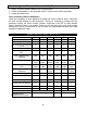
Specifications and Parts List
Model # A304 A306 A506 A308 A310 A510
Max. Watts 7500 7500 12500 7500 7500 12500
Max. single-pole circuits 4 6 6 8 10 10
Max. double-pole and multi-
wire
circuits
2 3 3 4 5 5
# of handle ties provided
1
1
1
2
2
2
Max. combined loads @ 125
VAC
60A 60A 100A 60A 60A 100A
Max. combined loads
@250VAC
30A 30A 50A 30A 30A 50A
Max. load/circuit from generator
2-30A
2
-
20A
2-30A
4
-
20A
2-30A
4
-
20A
2-30A
6
-
20A
2-30A
8
-
20A
2-30A
8
-
20A
Max. load/circuit from load
center
2-30A
2
-
20A
2-30A
4
-
20A
2-30A
4
-
20A
2-30A
6
-
20A
2-30A
8
-
20A
2-30A
8
-
20A
Power inlet, NEMA*
configuration
L14-30 L14-30 CS6375
non-NEMA
L14-30 L14-30 CS6375
non-NEMA
Minimum cord gauge AWG 10 AWG 10 AWG 6 AWG10 AWG 10 AWG 6
No. of conductors (wires) 4 4 4 4 4 4
Conduit length 18” 18” 18” 18’ 18” 18”
Conduit, trade-size diameter ¾” ¾” ¾” 1” 1” 1”
Optional Power Inlet Catalog #
PB30 PB30 PB50 PB30 PB30 PB50
*National Electrical
Manufacturer's Association