Instruction Manual RESIDENTIAL GAS W ATER HEA TERS WA HEATERS NOT FOR USE IN MANUFACTURED (MOBILE) HOMES Everything you need to know is contained in this fully illustrated Installation Guide. For most of you, this simple procedure booklet is all that’s needed. However, if necessary you can get help from “HELPFUL HAL”. He is there to help, with advice and direction.
SAFE INST ALLA TION INSTALLA ALLATION TION,, USE AND SERVICE Your safety and the safety of others is extremely important in the installation, use and servicing of this water heater. Many safety-related messages and instructions have been provided in this manual and on your own water heater to warn you and others of a potential injury hazard. Read and obey all safety messages and instructions throughout this manual.
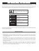
GENERAL SAFETY 3
TABLE OF CONTENTS SAFE INSTALLATION, USE AND SERVICE .............................. 2 GENERAL SAFETY .................................................................. 3 TABLE OF CONTENTS .............................................................. 4 INTRODUCTION ........................................................................ 4 Preparing for the New Installation ................................... 4 TYPICAL INSTALLATION .......................................................
TYPICAL INST ALLA TION INSTALLA ALLATION GET TO KNOW YOUR WATER HEATER - GAS MODELS A B C D E F G H VENT PIPE DRAFT HOOD ANODE HOT WATER OUTLET OUTLET INSULATION GAS SUPPLY MANUAL GAS SHUT-OFF VALVE I J K L M N O P GROUND JOINT UNION DRIP LEG (SEDIMENT TRAP) INNER DOOR OUTER DOOR UNION INLET WATER SHUT-OFF VALVE COLD WATER INLET INLET DIP TUBE Q R S T U V W X TEMPERATURE-PRESSURE RELIEF VALVE RATING PLATE FLUE BAFFLE(S) THERMOSTAT DRAIN VALVE PILOT AND MAIN BURNER FLUE DRAIN PAN * INSTALL IN ACCORDANC
TYPICAL INST ALLA TION INSTALLA ALLATION MIXING VALVE USAGE FIGURE 2. HOTTER WATER CAN SCALD: This appliance has been design certified as complying with ANSI Z21.10.3 latest edition, for water heaters and is considered suitable for: Water heaters are intended to produce hot water. Water heated to a temperature which will satisfy space heating, clothes washing, dish washing, and other sanitizing needs can scald and permanently injure you upon contact.
REMO VING THE OLD W ATER HEA TER REMOVING WA HEATER 4. Attach a hose to the water heater drain valve and put the other end in a floor drain or outdoors. Open the water heater drain valve. Open a nearby hot water faucet which will relieve pressure in the water heater and speed draining. The water passing out of the drain valve may be extremely hot. To avoid being scalded, make sure all connections are tight and that the water flow is directed away from any person, see Figures 3 and 6. FIGURE 6. 5.
MA TERIALS AND BASIC T OOLS NEEDED MATERIALS TOOLS DECIDING ON THE TYPE OF INSTALLATION Section B Copper (Sweat) Piping There are typically two different types of installations. The installation section of this manual has been broken into these two methods: The original piping is copper sweat and you are going to reconnect with sweat joints. Look at your old water heater installation to determine which type of installation you have.
LOCA TING THE NEW W ATER HEA TER OCATING WA HEATER FACTS TO CONSIDER ABOUT THE LOCATION • Water supply shut-off devices that activate based on the water pressure differential between the cold water and hot water pipes connected to the water heater. Carefully choose an indoor location for the new water heater, because the placement is a very important consideration for the safety of the occupants in the building and for the most economical use of the appliance.
This water heater must not be installed directly on carpeting. Carpeting must be protected by metal or wood panel beneath the appliance extending beyond the full width and depth of the appliance by at least 3” (76.2 mm) in any direction, or if the appliance is installed in an alcove or closet, the entire floor must be covered by the panel. Failure to heed this warning may result in a fire hazard. FIGURE 10.
per 1,000 Btu per hour (22cm2/kW) of the total input rating of all gas utilization equipment in the confined space, but not less than 100 square inches (645cm 2). One opening shall commence within 12” (30 cm) of the top and one commencing within 12” (30 cm) of the bottom of the enclosures. Insulation blankets are available to the general public for external use on gas water heaters but are not necessary with Reliance products.
a design of louver or grille is known, it should be used in calculating the size opening required to provide the free area specified. If the design and free area is not known, it may be assumed that wood louvers will be 20-25 percent free area and metal louvers and grilles will have 60-75 percent free area. Louvers and grilles shall be fixed in the open position or interlocked with the equipment so that they are opened automatically during equipment operation. FIGURE 13. 3.
INST ALLING THE NEW W ATER HEA TER INSTALLING WA HEATER FIGURE 16A. 3. Place the vent pipe over the draft hood. With the vent pipe in position, drill a small hole through both the vent pipe and draft hood. Secure them together with a sheet metal screw. 4. Wrap the 1” NPT threaded nipples (75 gallon models) or 1.25” NPT threaded nipples (100 gallon models) with teflon tape or pipe joint compound, see Figure 17. Connect the existing piping to the water heater. FIGURE 15.
8. After checking that all connections are tight and the drain valve near the bottom of the water heater is closed, go to “Filling the Water Heater”. FIGURE 20. SECTION B COPPER (SWEAT) PIPING (See Figure 19) FIGURE 20A. 3. Place the vent pipe over the draft hood. With the vent pipe in position, drill a small hole through both the vent pipe and draft hood. Secure them together with a sheet metal screw. 4.
shown. Clean the inside of each sweat fitting with the wire brush as shown. Make sure you do not touch the cleaned areas, see Figure 22. Flux the ends of the length of pipe cut for the T & P line and the inside of the 3/4” male threaded to sweat connector. Then solder this assembly together. Do not screw the connector into the Temperature-Pressure Relief Valve before the assembly is soldered together, see Figure 25. 13.
TEMPERATURE-PRESSURE RELIEF VALVE This heater is provided with a properly certified combination temperature - pressure relief valve by the manufacturer. FIGURE 27. The valve is certified by a nationally recognized testing laboratory that maintains periodic inspection of production of listed equipment of materials as meeting the requirements for Relief Valves for Hot Water Supply Systems, ANSI Z21.22•CSA 4.4 and the code requirements of ASME.
The temperature-pressure relief valve must be manually operated at least once a year. Caution should be taken to ensure that (1) no one is in front of or around the outlet of the temperature-pressure relief valve discharge line, and (2) the water manually discharged will not cause any bodily injury or property damage because the water may be extremely hot. actuated vent dampers). Before installation of any vent damper, consult the local gas utility for further information.
FIGURE 28. There must be a minimum of 6” (153 mm) clearance between single wall vent pipe and any combustible material. Fill and seal any clearance between single wall vent pipe and combustible material with mortar mix, cement, or other noncombustible substance. For other than single wall, follow vent pipe manufacturer’s clearance specifications. To insure a tight fit of the vent pipe in a brick chimney, seal around the vent pipe with mortar mix cement.
piping system at test pressures equal to or less than 1/2 pound per square inch (3.5kPa). If a standard model is installed above 2,000 feet (610 m) or high altitude model is installed above 4,500 feet (1,370 m), the input rating should be reduced at the rate of 4 percent for each 1000 feet (305 m) above sea level which requires replacement of the burner orifice in accordance with National Fuel Gas Code ANSI Z223.1/NFPA 54 or Contact your local gas supplier for further information.
FOR YOUR SAFETY READ BEFORE LIGHTING WARNING: If you do not follow these instructions exactly, a fire or explosion may result causing property damage, personal injury or loss of life. BEFORE LIGHTING: ENTIRE SYSTEM MUST BE FILLED WITH WATER AND AIR PURGED AT FAUCETS. A. This appliance has a pilot which must be lighted by hand. When lighting the pilot, follow these instructions exactly. BEFORE LIGHTING: smell all around the appliance area for gas.
FOR YOUR SAFETY READ BEFORE LIGHTING WARNING: If you do not follow these instructions exactly, a fire or explosion may result causing property damage, personal injury or loss of life. BEFORE LIGHTING: ENTIRE SYSTEM MUST BE FILLED WITH WATER AND AIR PURGED AT FAUCETS. A. B. • This appliance has a pilot which must be lighted by hand. When lighting the pilot, follow these instructions exactly. BEFORE LIGHTING: smell all around the appliance area for gas.
TEMPERA TURE REGULA TION TEMPERATURE REGULATION Short repeated heating cycles caused by small hot water uses can cause temperatures at the point of use to exceed the thermostat setting by up to 30°F (16.7°C). If you experience this type of use you should consider using lower temperature settings to reduce scald hazards. on the thermostat, read the “Temperature Regulation” section in this manual, see Figures 31 and 32. Never allow small children to use a hot water tap, or to draw their own bath water.
expansion tank or device to relieve the pressure built by thermal expansion in the water system. Expansion tanks are available for ordering through a local plumbing contractor. Contact the local water heater supplier or service agency for assistance in controlling these situations. c. Large amounts of hot water are used in a short time and the refill water in the tank is very cold.
HYDROGEN GAS: Hydrogen gas can be produced in a hot water system that has not been used for a long period of time (generally two weeks or more). Hydrogen gas is extremely flammable and explosive. To prevent the possibility of injury under these conditions, we recommend the hot water faucet, located farthest away, be opened for several minutes before any electrical appliances which are connected to the hot water system are used (such as a dishwasher or washing machine).
intact. Replacement of a depleted anode rod can extend the life of your water heater. Inspection should be conducted by a qualified technician, and at a minimum the anode(s) should be checked annually after the warranty period. BURNER CLEANING If inspection of the burner shows that cleaning is required, turn ) to the “OFF” position, the gas control knob clockwise ( depressing slightly.
The water heater should be drained if being shut down during freezing temperatures. Also periodic draining and cleaning of sediment from the tank may be necessary. valve and retighten using a wrench. DO NOT OVER TIGHTEN. 6. Follow instructions in the “Filling The Water Heater” section. 1. Turn the gas control knob to the “OFF” position. 7. Check for leaks. 2. CLOSE the cold water inlet valve to the water heater. 8.
LEAKAGE CHECKPOINTS A. Water at the draft hood is water vapor which has condensed out of the combustion products. This is caused by a problem in the vent. Contact the gas utility. B. *Condensation may be seen on pipes in humid weather or pipe connections may be leaking. C. *The anode rod fitting may be leaking. D. Small amounts of water from the temperature-pressure relief valve may be due to thermal expansion or high water pressure in your area. E.
TROUBLESHOOTING GUIDELINES These guidelines should be utilized by a qualified service agent. Problem Cause Solution Improperly sealed, hot or cold supply connection, Tighten threaded connections. relief valve, drain valve, or thermostat threads. WATER LEAKS LEAKING T&P VALVE Leakage from other appliances or water lines. Inspect other appliances near water heater. Condensation of flue products. Refer to CONDENSATION. Thermal expansion in closed water system.
REP AIR P ARTS LIST REPAIR PARTS Key No.
RESIDENTIAL GAS WARRANTY THIS WARRANTY IS APPLICABLE TO THE ORIGINAL OWNER ONLY. In accordance with the warranty terms and conditions specified below. • • • Reliance Water Heaters (the warrantor) will furnish the ORIGINAL OWNER, 1) a replacement Reliance water heater of equivalent size and current model if the glass-lined tank in this water heater leaks and, 2) a replacement part for any component part which fails.
INSTALLATION, OPERATION, REPAIR OR REPLACEMENT OF THE HEATER OR PARTS. THE WARRANTOR SHALL NOT BE RESPONSIBLE FOR WATER DAMAGE, LOSS OF USE OF THE UNIT, INCONVENIENCE, LOSS OR DAMAGE TO PERSONAL PROPERTY, OR OTHER CONSEQUENTIAL DAMAGE. THE WARRANTOR SHALL NOT BE LIABLE BY VIRTUE OF THIS WARRANTY OR OTHERWISE FOR DAMAGE TO ANY PERSONS OR PROPERTY, WHETHER DIRECT OR INDIRECT, AND WHETHER ARISING IN CONTRACT OR IN TORT.
500 Lindahl Parkway Ashland City, TN 37015 www.reliancewaterheaters.