Instruction Manual for Residential Power Direct Vent Gas Water Heaters NOT FOR USE IN MANUFACTURED (MOBILE) HOMES GAMA certification applies to all residential gas water heaters with capacities of 20 to 100 gallons with input rating of 75,000 BTU/Hr. or less. ALL TECHNICAL AND WARRANTY QUESTIONS: SHOULD BE DIRECTED TO THE LOCAL DEALER FROM WHOM THE WATER HEATER WAS PURCHASED. IF YOU ARE UNSUCCESSFUL, PLEASE WRITE TO THE COMPANY LISTED ON THE RATING PLATE ON THE WATER HEATER.
General Safety WARNING WARNING Improper installation, adjustment, alteration, service or maintenance can cause DEATH, SERIOUS BODILY INJURY, OR PROPERTY DAMAGE. Refer to this manual or consult your local gas utility for further assistance. WATER HEATERS EQUIPPED FOR ONE TYPE GAS ONLY: This water heater is equipped for one type gas only. Check the model rating plate near the gas control valve for the correct gas. DO NOT USE THIS WATER HEATER WITH ANY GAS OTHER THAN THE ONE SHOWN ON THE MODEL RATING PLATE.
General Safety (cont’d) WARNING WARNING This water heater must not be installed directly on carpeting. Carpeting must be protected by a metal or wood panel beneath the appliance extending beyond the full width and depth of the appliance by at least 3 inches (76.2mm) in any direction, or if the appliance is installed in an alcove or closet, the entire floor must be covered by the panel. Failure to heed this warning may result in a fire hazard.
Table of Contents General Safety ...............................................................................................................................2-3 Table of Contents .........................................................................................................................4 Introduction .........................................................................................................................................5 Preparing for the New Installation ....................
Introduction Thank You for purchasing this water heater. When installed according to State and Local Codes and maintained according to the manufacturers instructions, it should give you years of trouble free service. WARNING This gas-fired water heater is design certified by CSA International under American National Standard/CSA Standard for Gas Water Heaters, ANSI Z21.10.1 • CSA 4.1 (current edition).
Typical Installation EXHAUST VENT TO OUTDOORS INTAKE FOR COMBUSTION AIR Vacuum Relief required by some codes (refer to local codes) AIR INTAKE PIPE COLD WATER INLET Some models are equipped with circulating loop fittings.
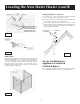
Locating the New Water Heater Facts to Consider About the Location 6. The location selection must provide adequate clearances for servicing and proper operation of the water heater. WARNING You should carefully choose an indoor location for the new water heater, because the placement is a very important consideration for the safety of the occupants in the building and for the most economical use of the appliance. This water heater is not for use in manufactured (mobile) homes or outdoor installation.
Locating the New Water Heater (cont’d) Facts to Consider About the Location (cont’d) venting system must be installed in a manner which allows • The inspection of the installation of the venting pipes and joints as WARNING Do not install in a confined area such a closet, unless you provide ventilation air as shown in the “Locating The New Water Heater” section. Never obstruct the flow of ventilation air. If you have any doubts or questions at all, call your gas company.
Locating the New Water Heater (cont’d) VENT OUTLET 61⁄2″ MIN. 24″ MAX. Venting Through Roof – Clearances AIR INTAKE clearance for 3″ PVC, ABS, or CPVC Schedule 40 piping • 0″ from combustible and noncombustible surfaces. 18 ″ ″ 18 vent exhaust outlet and air inlet terminals shall terminate at •The least 18 inches above the roof surface. Figure 7.
Installing the New Water Heater Water Piping WARNING INTAKE FOR COMBUSTION AIR HOTTER WATER CAN SCALD: Water heaters are intended to produce hot water. Water heated to a temperature which will satisfy clothes washing, dish washing, and other sanitizing needs can scald and permanently injure you upon contact. Some people are more likely to be permanently injured by hot water than others. These include the elderly, children, the infirm, or physically/mentally handicapped.
Installing the New Water Heater (cont’d) Temperature-Pressure Relief Valve WARNING WARNING At the time of manufacture this water heater was provided with a combination temperature-pressure relief valve certified by a nationally recognized testing laboratory that maintains periodic inspection of production of listed equipment or materials, as meeting the requirements for Relief Valves and Automatic Gas Shutoff Devices for Hot Water Supply Systems, and the current edition of ANSI Z21.
Installing the New Water Heater (cont’d) Filling the Water Heater You must provide all wiring of the proper size outside of the water heater. You must obey local codes and electric company requirements when you install this wiring. CAUTION If you are not familiar with electric codes and practices, or if you have any doubt in your ability to connect the wiring to this water heater, obtain the service of a competent electrician. Contact a local electrical contractor and/or the local electric utility.
Installing the New Water Heater (cont’d) 5. The water heater must be electrically “grounded” by the installer. The unit will not operate unless it is properly grounded. For complete grounding details and all allowable exceptions, refer to local codes or in the absence of local codes, with the National Electrical Code, ANSI/NFPA 70 (current edition). 6. Replace the wiring junction cover using the screws provided. Wiring Diagram CAUTION Label all wires prior to disconnection when servicing controls.
Installing the New Water Heater (cont’d) Venting (cont’d) 1. The water heater requires its own (separate) venting system. 2. Only 3″ ABS Schedule 40 piping and fittings are acceptable materials on the first five feet of the outlet vent system. 3. 3″ PCV, ABS, or CPVC Schedule 40 piping and fittings are acceptable materials for the inlet vent system and for the outlet vent system after the first five feet. 4. It cannot be connected to existing vent piping or chimney. 5.
Installing the New Water Heater (cont'd) VENTING SYSTEM EXAMPLE INSTALLATIONS FOR ALL MODELS 3 ELBOW EXAMPLE MIN. RISE 1⁄8″ PER FIVE FEET The vent piping cannot under any circumstances be run downhill. CAULK JOINT MIN. RISE 1⁄8″ PER FIVE FEET 2. The total vertical and horizontal vent runs cannot exceed the maximum length with the number of 90˚ elbows as specified in the table below.
Installing the New Water Heater (cont'd) Cementing PVC, ABS OR CPVC Pipe and Fittings VENT PIPE SEPARATION Read and observe all safety information printed on primer, cleaner, and cement containers. The inlet and outlet vent pipes must be separated by a minimum distance of 61⁄2 inches up to 24 inches maximum. DANGER 61⁄2″ MIN. 24″ MAX. Primer, cleaner, and cements are extremely flammable. They are harmful or fatal if swallowed. The vapors are harmful.
Installing the New Water Heater (cont'd) Venting (cont'd) INSTALLATION SHOWING USE OF PVC, ABS OR CPVC PIPE FOR INLET AND OUTLET VENT PIPING: INSTALLATION SHOWING USE OF (OPTIONAL) DELUXE HORIZONTAL VENT KIT: Inlet piping through any type wall. Typical installation. EXTERIOR WALL SILICONE SEALER VENT TO OUTDOORS AIR INTAKE PIPE INTAKE FOR COMBUSTION AIR 1 ⁄2″ MIN.
Installing the New Water Heater (cont’d) Gas Piping VENTING THROUGH A ROOF (CONT’D) 2. Only 3″ ABS Schedule 40 piping and fittings are acceptable materials on the first five feet of the outlet vent system of 75 Gal. Models and 50 Gal. 65,000 Btu/Hr Models only. 3. 3″ PVC, ABS, or CPVC Schedule 40 piping and fittings are acceptable materials for the inlet vent system and for the outlet vent system (after the first five feet for 75 Gal. Models and 50 Gal. 65,000 Btu/Hr Models only). 4.
Installing the New Water Heater (cont’d) GAS PIPING WITH FLEXIBLE CONNECTOR WARNING The appliance and its individual shutoff valve must be disconnected from the gas supply piping system during any pressure testing of that system at test pressures in excess of 1/2 pound per square inch (3.5kPa).
Installing the New Water Heater (cont’d) Installation Checklist BEFORE OPERATING THE WATER HEATER: 1. Check the gas line for leaks. a. Use a soapy water solution. DO NOT test for gas leaks using a match or open flame. b. Brush the soapy water solution on all gas pipes, joints and fittings. c. Check for bubbling soap. This means you have a leak. Turn “OFF” gas and make the necessary repairs. d. Recheck for leaks. e. Rinse off soapy solution and wipe dry. 2.
Operating This water heater is equipped with an electrically operated venting system and electronic control. For the burner to come on, the water heater thermostat must call for heat. Then the system will begin sequencing, each section proving itself before gas is allowed to flow to the burner. BLOWER MOTOR VENTING MANUAL RESET SWITCH BEFORE THE WATER HEATER WILL OPERATE: 1. The control system must be connected to a grounded 110/120 volt power supply. The control system has an overall rating of 2 amps.
Operating (cont’d) WARNING BEFORE OPERATING [PROPANE (L.P.) GAS WATER HEATERS]: Propane (L.P.) gas is heavier than air. Should there be a leak in the system, the gas will settle near the ground. Basements, crawl spaces, skirted areas under manufactured (mobile) homes (even when ventilated), closets and areas below ground level will serve as pockets for the accumulation of this gas.
Operating (cont’d) FOR YOUR SAFETY READ BEFORE OPERATING WARNING: If you do not follow these instructions exactly, a fire or explosion may result causing property damage, personal injury or loss of life. BEFORE OPERATING: ENTIRE SYSTEM MUST BE FILLED WITH WATER AND AIR PURGED FROM ALL LINES. A. This appliance does not have a pilot. It is equipped with an ignition device which automatically lights the burner. Do NOT try to light the burner by hand. B.
Temperature Regulation changing the temperature setting. To change the temperature setting follow these instructions: Due to the nature of the typical gas water heater, the water temperature in certain situations may vary up to 30°F higher or lower at the point of use such as, bathtubs, showers, sink, etc. 1. “Wake Up” the temperature indicators by holding down both “COOLER” and “HOTTER” temperature adjustment buttons at the same time for one second (See Figure below).
For Your Information Start Up Conditions CONDENSATION It is recommended that any devices installed which could create a closed system have a by-pass and/or the system have an expansion tank to relieve the pressure built by thermal expansion in the water system. Expansion tanks are available for ordering through local plumbing supply houses. Contact the local water supplier and/or plumbing contractor for assistance in controlling these situations.
For Your Information (cont’d) Operational Conditions (cont’d) “AIR” IN HOT WATER FAUCETS HIGH TEMPERATURE LIMIT SWITCH (Single-Use Type Energy Cut Off) The thermostat has a built-in limit switch which will actuate in case of excessive water temperatures. The heater cannot be relit until the gas control valve is replaced. It is important that a serviceman be called to determine the reason for limit operation and thus avoid repeated thermostat replacement.
Periodic Maintenance Venting System Inspection If proper flame characteristics are not evident, check for accumulation of lint or other foreign material that restricts or blocks the air openings in the heater or burner. Also check Combustion Air and Ventilation requirements. At least once a year a visual inspection should be made of the venting system. You should look for: 1. Obstructions which could cause improper venting. The combustion and ventilation air flow must not be obstructed. 2.
Periodic Maintenance (cont’d) Anode Rod Inspection L.P. Gas Control Valve & Burner Assembly Replacement Information The anode rod is used to protect the tank from corrosion. Most hot water tanks are equipped with an anode rod. The submerged rod sacrifices itself to protect the tank. Instead of corroding the tank, water ions attack and eat away the anode rod. This does not affect the water’s taste or color. The rod must be maintained to keep the tank in operating condition. WARNING PROPANE (L.P.
Periodic Maintenance (cont’d) Draining The water heater should be drained if being shut down during freezing temperatures. Also periodic draining and cleaning of sediment from the tank may be necessary. 1. Turn “OFF” gas supply to water heater. 2. CLOSE the cold water inlet valve to the water heater. 3. OPEN a nearby hot water faucet and leave open to allow for draining. 4. Connect a hose to the drain valve and terminate to an adequate drain. 5. OPEN the water heater drain valve to allow for tank draining.
Leakage Checkpoints Use this guide to check a “Leaking” water heater. Many suspected “Leakers” are not leaking tanks. Often the source of the water can be found and corrected. CAUTION Read this manual first. Then before checking the water heater make sure the gas supply has been turned “OFF”, and never turn the gas “ON” before the tank is completely full of water. If you are not thoroughly familiar with gas codes your water heater, and safety practices, contact the gas utility to check the water heater.
Troubleshooting WARNING WARNING Label all wiring before disconnecting any wiring; to ensure correct reconnection. Failure to follow this instruction could cause improper and possible dangerous operation, resulting in DEATH, SERIOUS BODILY INJURY, OR PROPERTY DAMAGE. This troubleshooting guide has been supplied for use by qualified service personnel who have a complete understanding of both electricity and gas.
Troubleshooting (cont’d) SYSTEMS CHECK WARNING Please check guidelines below. For your safety, water heater service should be performed only by a qualified service technician. LED STATUS DO NOT BY-PASS ANY CONTROLS TO MAKE HEATER OPERATE. OPERATE ONLY AS WIRED FROM FACTORY. PROBLEM SOLUTION An open earth ground circuit to the ignition system. 1. Check that the earth ground connection is properly connected. 2. Check that the ground conductor on the water heater is properly connected.
Troubleshooting (cont’d) PROBLEM NOT ENOUGH HOT WATER VENT PIPE TOO HOT (ABOVE 170˚F) YELLOW FLAME CONDENSATION WATER LEAKS LEAKING T&P HOT WATER ODORS (Refer to CATHODIC PROTECTION WATER TOO HOT WATER HEATER SOUNDS SIZZLING-RUMBLING SOOTING HEATER LIGHTS BUT GOES OUT IN 4-5 SECONDS CAUSE SOLUTION Blower will not run. A) “ON/OFF” control switch turned off. B) Blower unplugged. C) No power at outlet. D) Thermostat defective. E) Control harness defective. F) High limit control circuit open.
Repair Parts 35 1 2 Outlet Parts Only 75 Gallon Models and 50 Gallon 65,000 Btu/Hr Models 3 4 5 6 8 7 9 11 10 33 32 12 31 14 13 30 29 29 28 15 27 21 26 20 24 25 16 19 18 22 34 23 17 34
Repair Parts (cont’d) KEY NO. 1. 2. 3. 4. 5. 6. 7. 8. 9. 10. 11. 12. 13. 14. 15. 16. 17. 18. 18. 18. 18. PART DESCRIPTION Vent Cap w/Screen Adaptor, Flue Mounting 5′ ABS Schedule 40 Vent Pipe 90° ABS Schedule 40 Elbow Vent/Blower Adapter Blower Flue Adaptor Gasket (6″ x 10.102″) Blower Gasket Venting; Manual Reset Switch Vent Hood Assembly Rubber Gasket – Wiring T&P Valve Dip Tube Anode Rod Wiring Harness Drain Pan Hot Surface Ignition Assembly Orifice (Natural) Standard Orifice (L.P.
Repair Parts 35 1 2 Outlet Parts Only 75 Gallon Models and 50 Gallon 65,000 Btu/Hr Models 3 4 5 6 8 7 9 11 10 33 32 12 31 14 13 30 29 29 28 15 27 21 26 20 24 25 16 19 18 22 34 23 17 36
Repair Parts (cont’d) KEY NO. 1. 2. 3. 4. 5. 6. 7. 8. 9. 10. 11. 12. 13. 14. 15. 16. 17. 18. 18. 18. 18. PART DESCRIPTION Vent Cap w/Screen Adaptor, Flue Mounting 5′ ABS Schedule 40 Vent Pipe 90° ABS Schedule 40 Elbow Vent/Blower Adapter Blower Flue Adaptor Gasket (6″ x 10.102″) Blower Gasket Venting; Manual Reset Switch Vent Hood Assembly Rubber Gasket – Wiring T&P Valve Dip Tube Anode Rod Wiring Harness Drain Pan Hot Surface Ignition Assembly Orifice (Natural) Standard Orifice (L.P.
Notes 38
Notes 39