SERVICE HANDBOOK FOR STANDARD RESIDENTIAL FVIR GAS WATER HEATERS MODELS: G/LORT, G/LORS, G/LBRT, G/LBRS, G/LBCT, G/LBCS,G/LKRT, G/LKRS, G/LKCT, G/LART, G/LARS, G/LXRT, G/LQRT – SERIES 200/201 and SERIES 202/203 11/09 RRTB001109 317667-000
SERVICE HANDBOOK Your safety and the safety of others is extremely important in the servicing of this water heater. Many safetyrelated messages and instructions have been provided in this handbook and on your water heater to warn you and others of a potential hazard. Read and obey all safety messages and instructions throughout this handbook. It is very important that the meaning of each safety message is understood by you and others who service this water heater.
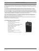
Fire or Explosion Harzard Do not store or use gasoline or other flammable vapors and liquids in the vicinity of this or any other appliance. Avoid all ignition sources if you smell Natural or LP gas. Do not expose water heater control to excessive gas pressure. Use only gas shown on rating plate. Maintain required clearances to combustibles. Keep ignition sources away from faucets after extended period of non-use. Read instruction manual before installing, using or servicing water heater.
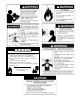
TROUBLESHOOTING QUICK REFERENCE IMPORTANT: Before performing any test, check the area around the water heater for any source of a flammable vapor (i.e gasoline, paint thinners, etc.) If any sources are found do not proceed until they are removed. PROBLEM POSSIBLE CAUSE TEST / CORRECTIVE ACTION Insufficient Combustion Air or Venting Issues – combustion chamber thermal cut off tripped. Follow the steps on pp 18 – 19. Always check and clean the base ring filter and the flame arrestor.
PROBLEM POSSIBLE CAUSE TEST / CORRECTIVE ACTION Thermostat does not shut-off Check the Gas Control Valve/Thermostat as described on p. 20-21. Drain valve dripping/leaking Back flush to clean- out sediment, replace if necessary Tank Leak Check Leakage Checkpoints described on p. 25.
TABLE OF CONTENTS BASIC INSTALLATION ...................................................................................................................................... 8-16 DRAINING AND FILLING THE WATER HEATER..................................................................................................17 Draining the Water Heater ................................................................................................................................17 Filling the Water Heater ...............
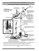
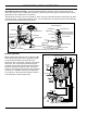
BASIC INSTALLATION & OPERATION INSTALLATION OF RESIDENTIAL GAS WATER HEATER See Labels and Installation Instructions and Use & Care Guide for clearances. Exhaust Vent to Ouside of Building Union Union Untempered Hot Water Cold Water Inlet Water Shut-Off Valve *Massachusett: Install a vacuum relief in cold water line per section 19 MGL 142. Expansion Tank Pressurize to Equal Supply Water Pressure* (Relieve water pressure on the expansion tank before adjusting air pressure.
BASIC INSTALLATION & OPERATION This portion of this handbook applies to the Operations and Servicing of Residential Gas, Tank Type, Water Heaters, which are vented atmospherically and use a thermocouple as their electrical source. Control: There are two gas control valve/thermostat configurations available. Both valves have similar control elements such as the Gas Control Knob & Water Temperature Dial. Both valves have high water temperature limit safety.
BASIC INSTALLATION & OPERATION Burner/Manifold Door Assembly: The burner/manifold assembly consists of several components such as: main burner, burner orifice, manifold tube, pilot burner, pilot orifice, pilot tube, igniter, and thermocouple. See the figure below for the complete list of components. The pilot burner remains on once it is manually lit. When incoming cold water activates the thermostat, gas flows to the main burner. The pilot flame ignites this gas.
BASIC INSTALLATION & OPERATION Energy Cut Off (ECO): A metal tube (Temperature Probe) mounted onto the back of the gas control valve/thermostat is immersed inside the tank water. The probe acts as a temperature high limit. If water gets excessively hot, an Energy Cut Off (ECO) switch within the probe opens, interrupting the small electrical current to the gas valve, and gas flow through the control is interrupted. NOTE: If this safety sensor opens, the entire control must be replaced.
BASIC INSTALLATION & OPERATION Thermostat Operation: Standard residential water heaters use mechanical thermostats. With a mechanical thermostat, a dial setting of 120° F may shut the burner down at a tank temperature between 110° and 130° F. The heater will consistently shut off at this same temperature. For this same reason, water temperature may drop 15° F - 25° F, around the temperature probe, before the main burner is activated.
BASIC INSTALLATION & OPERATION Combustion Air Requirements: Table 1: WARNING BTUH Input 30,000 45,000 60,000 75,000 90,000 105,000 120,000 135,000 Carbon Monoxide Warning Water heater must be vented to outdoors. Vent must be installed by a qualified technician using the local and state codes or, in the absence of local and state codes, the National Fuel Gas Code, ANSI Z223.1 (NFPA 54) - current edition, and/or the installation instructions.
BASIC INSTALLATION & OPERATION All Air from Inside the Building: When additional air is to be provided to the confined area from additional room(s) within the building, the total volume of the room(s) must be of sufficient size to properly provide the necessary amount of fresh air to the water heater and other gas utilization equipment in the area.
BASIC INSTALLATION & OPERATION Vent Connectors: 1 SQ. INCH PER 2000 BTUH 100 SQ. INCH MINIMUM (EACH) 1. 2. Single wall Vent Pipe. Maintain the manufacturer’s specified minimum clearance from combustible materials when using type B double wall vent pipe. OUTLET CONFINED SPACE Vent connectors made of type B, double wall vent pipe material may pass through walls or partitions constructed of combustible material if the minimum listed clearance is maintained.
BASIC INSTALLATION & OPERATION • The connector must be firmly attached and sealed to prevent it from falling out. • To aid in removing the connector, a thimble or slip joint may be used. • The connector must not extend beyond the inner edge of the chimney as it may restrict the space between it and the opposite wall of the chimney The following figures are examples of vent pipe system installations and may or may not be typical for your specific application.
DRAINING AND FILLING THE WATER HEATER Filling the Water Heater Draining the Water Heater The water heater should be drained if being shut down during freezing temperatures. Also, periodic draining and cleaning of sediment from the tank may be necessary. 1. Turn off the gas to the water heater at the manual gas shut-off valve. 2. Open a nearby hot water faucet until the water is no longer hot. Never use this water heater unless it is completely full of water.
CHECKING THE GAS SUPPLY PRESSURE Checking the Gas Supply Pressure • Supply gas pressure checks are measured before the gas control valve/thermostat and as close to the water heater as possible. • Manifold (main burner) gas pressure is measured at the pressure tap on the bottom of the gas control valve/thermostat. Use an Allen wrench to remove the plug then attach the gas gauge.
CHECKING FOR SUFFICIENT COMBUSTION AIR OR VENTING ISSUES Draft Test After successfully lighting the water heater, allow the unit to operate for 15 minutes and check the draft hood relief opening for proper draft. Make sure all other appliances in the area are operating and all doors/windows are closed when performing the draft test. Pass a match flame or smoke around the relief opening of the draft hood. A steady flame or smoke drawn into the opening indicates proper draft.
TESTING THE THERMOCOUPLE AND GAS CONTROL VALVE/THERMOSTAT IMPORTANT: Before performing any test, check the area around the water heater for any source of a Flammable Vapor (i.e gasoline, paint thinners, etc.) If any sources are found do not proceed until they are removed. Thermocouple Output Test The following test will check the DC voltage generated by the thermocouple when the pilot light is lit. 1. Disconnect the thermocouple from the gas control valve/thermostat as shown in the adjacent figure. 2.
REPLACING THE THERMOCOUPLE AND GAS CONTROL VALVE/THERMOSTAT Removing the Manifold/Burner Assembly 1. Turn off the gas supply to the water heater at the manual gas shut-off valve. This valve is typically located beside the water heater. Note the position of the shut-off valve in the open/on position then proceed to turn it off. 2. On the lower front of the water heater locate the gas control valve/thermostat.
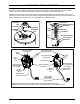
REPLACING THE THERMOCOUPLE AND GAS CONTROL VALVE/THERMOSTAT FERRULE NUT THERMOCOUPLE IGNITER WIRE PILOT PILOT BRACKET OTHER FITTINGS NOT SHOWN FOR CLARITY RETAINER CLIP MANIFOLD TUBE PILOT TUBE TWO PIECE WIRE CONNECTOR MANIFOLD/BURNER DOOR OPENING Figure 25 Replacing the Manifold/Burner Assembly WARNING Explosion Hazard • Tighten both manifold door screws securely. • Remove any fiberglass between gasket and combustion chamber. • Replace viewport if glass is missing or damaged.
REPLACING THE THERMOCOUPLE AND GAS CONTROL VALVE/THERMOSTAT 7. CLOSE-UP INSIDE VIEW OF THE COMBUSTION CHAMBER. SLOT TIP MANIFOLD TUBE To remove the gas control valve/thermostat, thread a correctly sized pipe into the inlet and use it to turn the gas control valve/thermostat (counterclockwise.) Do not use pipe wrench or equivalent to grip body. Damage may result, causing leaks. Do not insert any sharp objects into the inlet or outlet connections. Damage to the gas control valve/ thermostat may result.
ADJUSTING THE TEMPERATURE ON THE GAS CONTROL VALVE THERMOSTAT Water temperature over 125°F (52°C) can cause servere burns instantly resulting in severe injury or death. Children, the elderly, and the physically or mentally disabled are at highest risk for scald injury. Feel water before bathing or showering. reset to the desired temperature setting to reduce the risk of scald injury.
GAS WATER HEATER SIZING GUIDE Use the following information as a guide to approximate the correct size water heater for the residence: • 30 gallon size (21 gallon draw) for one bath residence. • 40 gallon size (28 gallon draw) for two bath residence -or one bath with an automatic clothes washer. • 50 gallon size (35 gallon draw) for three bath residence - or two baths with an automatic clothes washer.
TECHNICAL BULLETINS WATER HAMMER ..................................................................................................................................................27 MINERAL BUILD-UP ..............................................................................................................................................28 ALUMINUM HYDROXIDE ......................................................................................................................................
BULLETIN 11 WATER HAMMER GENERAL Water hammer is the destructive force, pounding noise and vibration in a piping system when water flowing through a pipeline is stopped abruptly. When water hammer occurs, a high intensity pressure wave travels back through the piping system until it reaches a point of some relief. The shock wave will then surge back and forth between the point of relief and the point of stoppage until the destructive energy is dissipated in the piping system.
BULLETIN 13 MINERAL BUILD-UP SYMPTOMS • Rumbling • Crackling • Popping CAUSE With the increase in fuel costs and hot water consumption, deliming has become a necessity of modern maintenance. Lime (CaCO3), is the most notable factor when discussing water hardness. Lime is present in every water system to some degree.
BULLETIN 14 ALUMINUM HYDROXIDE SYMPTOMS “Crackling”, “gurgling”, or “popping” noises from new water heaters (installed less than six months). CAUSE In a few isolated parts of the United States where the water supply has a relatively high pH (8+), water conditions will react with the aluminum anode to form excessive amounts of aluminum hydroxide on the anode and in the bottom of the tank.
BULLETIN 15 CONDENSATION SYMPTOMS The water heater appears to be releasing water while the main burner is on or water is found surrounding the heater shortly after the water heater has been used. This bulletin explains why flue gases condense and how you can differentiate between condensation and leaking. CAUSES Condensate is the result of air borne water vapor being chilled below the dew point. The dew point is the temperature at which water vapor turns into liquid.
BULLETIN 21 DISCOLORED WATER SYMPTOMS Rusty, brown, black, or yellow water appearing in the hot water. CAUSES Complaints of discolored water are commonly blamed on water heaters and storage tanks, but in fact, it is a rare occurrence for today’s high quality glass lined tanks to have a lining failure significant enough to allow water to contact enough bare metal to discolor the contents of even a small tank.
BULLETIN 22 SMELLY WATER CAUSES The most common cause of “smelly water” is a non-toxic sulfate reducing bacteria, scientifically termed Divibrio Sulfurcans. This bacteria often enters the water system through construction or a break in ground piping. The bacteria creates the energy it needs to survive by converting sulfate (SO4) to hydrogen sulfide(H2S) gas you smell in the water. Hydrogen sulfide gas is distinctive because of its rotten egg-like stench.
BULLETIN 23 CHLORINATION PROCEDURE CAUSES The chlorination procedure is used to eliminate various bacteria that accumulate and grow in water heaters. These bacteria often cause odorous or discolored water conditions. PROCEDURE Please read the steps of the chlorination procedure prior to beginning. If you feel uncomfortable performing any of these steps, contact a service person to perform this procedure for you. STEP 1 Turn off the gas or electric supply to the tank.
BULLETIN 35 NOT ENOUGH HOT WATER - GAS CAUSES Complaints regarding an insufficient supply of hot water are typically the result of a water heater that cannot meet the demands of the residence (both people and appliances). The demand for sufficient hot water may also be exceeded if additional people and/or appliances are added to the residence. Another factor that may reduce the hot water output is mineral build-up.
BULLETIN 45 THERMAL EXPANSION SYMPTOMS • • • • • • • CAUSE Effects are only noticeable after hot water use followed by periods of no water use. Relief valve drips during any recovery cycle when no hot or cold water is used. Hot water pipes creak while heater is recovering and all valves are closed. Tanks or other components of the water supply system fail prematurely.
THERMAL EXPANSION THE FIX The ideal fix involves the use of a pressure reducing valve if supply pressures are above 60 to 70 psi, and a properly sized expansion tank. The PRV reduces supply pressures to 40 to 60 psi allowing an economically priced and sized expansion tank to be used. The PRV also offers the benefit of saving water and prolonging the life of water flow valves. The PRV is not required if the system already has one or if high supply pressures are desired.
BULLETIN 52 LEAKING TEMPERATURE AND PRESSURE RELIEF VALVE SYMPTOMS • • • • Water seeping around the relief valve tank connection Leakage at the threaded portion of the relief valve connection Intermittent weeping and/or dribbling from the relief valve Large volume of hot water sporadically discharged from the relief valve GENERAL The temperature and pressure relief valve (T & P) is a safety device limiting temperature and pressure levels in a water heater.
BULLETIN 60 INSULATION BLANKETS GENERAL The purpose of an insulation blanket is to reduce the standby heat loss encountered with storage tank heaters. Most modern water heaters have adequate factory installed insulation, the use of an after market insulation blanket is no longer recommended by most experts. While the use of an external insulation blanket will not void the warranty, the water heater manufacturer explicitly disclaims any liability for problems associated with the use of insulation blankets.
GENERAL INFORMATION Draw efficiency is the quantity of hot water available to the consumer before the outlet water temperature decreases 25 degrees F. A 40 gallon water heater will typically provide 70% (28 gallons) of this “usable” hot water (60% is the minimum). The burner or elements are allowed to operate during this test. Incoming, cold water mixes the remaining stored water below this 25 degree limitation.
GENERAL INFORMATION One pound of gas pressure is equal to 27.7 inches water column pressure Inches of Water Column X .036091 = PSI Inches of Water Column X .073483 = Inches of Mercury (Hg.) Centimeters = Inches X 2.54 MM (millimeters) =Inches X 25.4 Meters = Inches X .0254 Doubling the diameter of a pipe will increase its flow capacity (approximately) 5.3 times. Construction: Tank is constructed of steel. The inside of the tank is constructed of a glass lining bonded to the steel.
NOTES 41
NOTES 42
FOR ASSISTANCE, CONTACT RELIANCE WATER HEATERS RESIDENTIAL TECHNICAL ASSISTANCE 1-800-365-4054 OR WWW.RELIANCEWATERHEATERS.COM.