
User's Manual

PRELIMINARY
PRELIMINARY PRELIMINARY
PRELIMINARY –
––
–
Service
ServiceService
Service Manual
Manual Manual
Manual
DR• CHKD• APPD•
28
Circuit Description
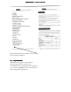
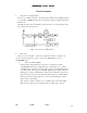
3. Frequency configuration
The receiver utilizes double conversion. The first IF is 38.85MHz and the
second IF is 450KHZ. The first local oscillator signal is supplied from the
PLL circuit.
The PLL circuit in the transmitter generates the necessary frequencies.
Fig.1 shows the frequencies.
Fig1. Frequency configuration
4
.
Receiver
The receiver is double conversion superheterodyne, designed to
operate in the frequency range of 150-174 MHz (M type), 136——
150MHZ
•M2
type
••
1
)
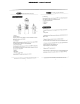
Front-end RF amplifier
An incoming signal from the antenna is applied to an RF
amplifier(Q203) after passing through a transmit/receive switch
circuit(D 102 and D103 are off ) and a band pass filter(L208, L209
and L210). After the signal is amplified(Q203), the signal is filtered
through a band pass filter (L203 and L214) to eliminate unwanted
signals before it is passed to the first mixer. Band pass filters (L208,
L209, L210, L203 and L214) have varactor diodes (D203, D204,
D206, D202 and D201).
The voltage of these diodes are controlled by to track the MPU
(IC403) center frequency of the band pass filter. (See Fig. 2)