THANK YOU! We are grateful for your purchase of the product. We believe this easy–to-use radio will provide you with dependable and reliable communications. This portable two-way radio is a precision device. Treat it with care, and you will enjoy years of reliable operation.
Contents Safety and General Information Product Safety and RF Exposure Compliance FCC Licensing Information Products Inspection Battery Information Antenna Information Accessory Installation Battery Antenna Belt Clip Earplug Cover External Earphone/Microphone (optional) Getting Started Features and Operation Turn on/off the radio Adjust the Volume Power-on Password (only for keypad model) Keypad Lock/Unlock (only for keypad model) Select Channel Transmit Receive Monitor Repeater/Talk Around Repeater/ Rever
Frequency Chart Safety and General Information The following general safety precautions as would normally apply, should be observed during all phases of operation, service and repair of this equipment. ! This equipment should be serviced by qualified technicians only. ! Do not modify the radio for any reason. ! Use only the original batteries and chargers. ! Use only the supplied or an approved antenna. ! Do not use any portable radio that has a damaged antenna.
! When transmitting with a portable radio, hold the radio in a vertical position with the microphone 5 centimeters away from your lips. ! If you wear a radio on your body, ensure the radio and its antenna is at least 2.5 centimeters away from your body when transmitting. WARNING: If you wear a radio on your body, ensure the radio and its antenna is at least 2.5 centimeters away from your body when transmitting.
! Ministry of Health (Canada) Safety Code 6.
! Use only the approved, supplied batteries or the approved replacement batteries. Use of non-approved batteries may exceed FCC RF exposure guidelines. FCC Licensing Information This equipment has been tested and found to comply with the limits for a Class B digital device, pursuant to part 15 of the FCC Rules. These limits are designed to provide reasonable protection against harmful interference in a residential installation.
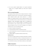
items listed in the following table are enclosed before discarding the box. If any items are missing or have been damaged during shipment, file a claim with the carrier immediately. Available Accessories Item Qty. (pcs) Antenna* 1 Belt Clip 1 Strap 1 Battery 1 Desktop Charger 1 AC Adapter 1 Owner’s Manual 1 *Notes: ① Frequency is marked on the color circle of the antenna. Red circle indicates UHF and green indicates VHF.
human injury, treat any battery with care. 2. Do not short out the battery terminals or dispose of the battery in fire. Never attempt to disassemble the battery. If discarded, the battery should be thrown into dedicated battery recycle box. Normal operation Please charge the battery indoor to ensure the optimal charging effect. In general, the battery can be removed if the charger indicator turns from red to green. Turn off the radio when charging the battery inside the radio.
LED Indication Flashing red Low battery voltage Red Charging Green Fully charged 1. Plug the power cable into the adapter. 2. Plug the DC socket of adapter into the DC jack on the rear of the charger. 3. Insert the battery or the radio with battery into the charger cup. 4. Plug the AC socket of adapter into an AC outlet. 5. Make sure that the battery connectors are in contact with the charging terminals; the charger LED glows red and charging begins. 6.
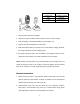
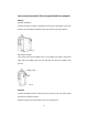
Accessory Information (Take a keypad model for example) Battery Attaching the battery: Insert the two tabs on bottom of the battery into the slots at the bottom of the radio. Push the top of the battery towards the radio until a click is heard. (See figure 1) Fig. 1 Removing the battery: Turn off the radio. Push the battery latch on the middle of the radio to remove the upper side of the battery away from the radio and then remove the battery. (See figure 2) Battery Latch Fig.
Attach Remove Fig. 3 Belt Clip Attaching Belt Clip: Align the slot of the belt clip with the T-slot at the battery cover and press the belt clip downwards until it is locked. (See figure 4) Fig. 4 Removing the belt clip: Press the disassembly release upwards with a key until it releases and then push the belt clip upwards with your thumb to remove it. (See figure 5) Disassembly Release Fig.
Earphone/Microphone Jack Cover To remove the Earphone/Microphone jack cover, rotate the screw at the bottom of the cover counterclockwise with a screwdriver until it is free. (See figure 6) Fig. 6 External Earpiece/Microphone (Optional) Insert the tab at the bottom of the earphone/microphone into the slot on the radio. (See figure 7). Align the thumbscrew at top of the earphone/microphone with the hole on the radio and turn it clockwise to fasten. Fig.
Getting Started (Keypad type model) (1) Antenna Used to transmit/receive signals. (2) LED The following table indicates LED mode and corresponding radio status: LED Status Not lit Standby Green Receive Red Transmit Flashing green Scan Flashing red Low battery voltage Flashing orange Call waiting (3) Channel Selector Used to select wanted channel.
(5) Power/Volume Control Knob Rotate the Power/Volume Knob clockwise until a “click” is heard to turn the radio on; rotate fully counter-clockwise to turn the radio off. When the radio is on, turn the knob to adjust volume. (6) Battery Latch Used to fasten the battery. (7) Speaker Used to output receiver audio and alert tones (8) Microphone Used to input voice audio (9) External Jack Used to connect with external earphone or programming cable.
Repeater/Talk Around Repeater/Reverse Frequency Select Repeater or Talk Around Mode Select Repeater or Reverse Frequency Mode Select Repeater or Talk Around Mode Select Repeater or Reverse Frequency Mode Radio Call Transmit a Call Transmit a Call Selective Call Transmit selective call or group call signalling (2-Tone) or MDC shortcut key Transmit selective call or group call signalling (2-Tone) or MDC shortcut key Vibration Toggle Vibration On/off Toggle Vibration On/off Priority Channel Set Se
Fig.
Features and Operation Turn On/Off the Radio To turn the radio on, rotate the “Power/Volume” knob clockwise. An alert tone indicates that the self-test of the radio completed successfully. The LED glows green during power-up. If self-test fails and/or the selected channel is not set, you will also hear an alert tone. To turn the radio off, rotate the “Power/Volume” knob counterclockwise until a click is heard. Adjust the Volume Rotate the “Power/Volume” knob to adjust the volume.
2. Rotate the “Channel Selector” knob to select the wanted channel. 3. Make sure there is no activity on the channel. 4. Press the PTT key and speak into the microphone with your mouth 1- 2 inches away from the radio. The LED glows red during transmission. 5. Release the PTT key to finish transmission. Receive 1. Turn on the radio. 2. Rotate the “Channel Selector” knob to select the wanted channel. 3. Adjust the volume. 4.
status after the Monitor key is released. Repeater/Talk Around When you are out of the communication range of the repeater and within the communication range of your group member, you can bypass the repeater and talk directly to your group member. Press the programmed Repeater/Talk Around key to select between “repeater” and “talk around” mode. An alert tone indicates that radio is in talk around mode (simplex). A different alert tone indicates that the radio is out of the talk around mode (duplex).
Scan Scan feature allows you to monitor activities on all channels for receiving call from these channels. When scan feature is enabled, the radio will detect calls from all channels. If an active channel is detected, the radio will switch to that channel so that to receive an incoming call(Channels must be programmed to be included in scan list). Disable/Enable Scan Feature 1. Press the scan key to begin scanning. 2. Press the scan key again to stop scanning. The LED flashes green in scan mode.
Call Press the programmed call key and the radio will send a preprogrammed signalling code to compatible receivers with the same code. The compatible receiver is revived and sounded an alert tone to draw the user’s attention. Selective Call by Signalling If Selective Call by Signalling is set in radio, specific radio will be selectively called through this function. Selective Call only has 2-tone signalling.
1. Press Record key or select Record feature in the menu to begin record. 2. When the memory is full and a new message is received, the oldest unprotected message will be deleted. Unread message will not be deleted. 3. The radio stops recording when the record time elapses or any valid key is pressed or when signal appears. 4. The radio can be set to delete all messages after power off (set by your dealer). Play 1.
must be preset by programming software). 5. Press PTT key to transmit, then an alert tone will be sounded after transmission. Radio will enter call waiting mode after it exits from menu mode. 6. Press PTT key to transmit, release it to receive. 7. Exit call waiting mode after reset. Receive Selective Call When user receives selective call, he will: 1. Hear the characterized alert tone that set by himself. 2. LED will flashes orange. 3.
calling to be displayed alternatively. Press PTT key to response this information page, terminate characterized alert tone, and press any key to clean up the displayed content after exit from call waiting. Radio Check This function allows user to determine whether radio is in the range of disturbing himself. Radio check is activated when failure happens after trying selective call and call alert. This function only is used when radio signalling agreement support it. Enforce a radio check: 1.
Alert Tone High tone Low tone Operation Description Turn on the radio Power on-Ready Turn on the radio Power on-Failure Repeater/Talk Around Repeater Repeater/Talk Around Talk Around Repeater/Reverse Repeater Frequency Repeater/Reverse Reverse Frequency Frequency Select Power High Power Select Power Low Power Low Battery Alert Tone Idle Channel Tone PLL Unlock Tone 25 Audible Tone
Menu Radio Check Radio Alert Unread MSG Alert Selective Call Play Delete Protect Delete All MSG Record Message Option Backlight Power Level VOX Level Off 1, 2, 3 Menu Mode (Functions are subject to addition without prior notice) MDC function Voice Service Channel Number /Alias/Frequency English Level1-Level8 Zone 1-Zone 16 Squelch Level 26 Channel Display Language Talk Around/ Reverse Frequency Tone Level Utilities Select Zone Modify Name of Selective Call Selective Call Edit
Selective Call List 1. Press key in squelch standby mode to enter the main menu and go to the “ Selective call” item. Press [C] key to exit from the menu mode. Selective Call 2. Press key to enter selective call list and then press◄/►key to select selective call name. Press key to save the change and exit from the menu. Press [C] key to return to the upper menu without saving the change. Simon Edit Selective Call Alias (By Keypad) 1.
Note: Selective call alias can only be typed in English. To type in Chinese, user should edit through programming software. Select Zone 1. Press ►key to enter “select zone” item. Select Zone 2. Press key to enter the zone list (1-16) and press ◄/►key to select a zone. Press key to save the selected zone and return to the main menu. Press [C] key to return to the main menu without saving the change. Zone 6 Utilities Squelch Level 1. Press ►key to enter “Utilities” menu. Utilities 2.
VOX Level 1. Enter the “Utilities” menu. Utilities 2. Press ►key to go to VOX item. Press key to enter the item. LCD displays current VOX level. VOX Level 1 3. Press ◄/►key to change the VOX level (off, level 1-3). VOX feature is disabled when “OFF” is displayed. Press key to save the change and return to the utilities menu. Press [C] key to quit without saving the change. 2 Power Level 1. Enter the “Utilities” menu. Utilities 2. Press ►key to go to “power level switch” item.
change. Power Low Backlight 1. Enter the “Utilities” menu. Utilities 2. Press ►key to go to “backlight” item. Press key to enter the item. LCD displays backlight option. Backlight Off 3. Press ◄/►key to turn the backlight on/off. Press key to save the change and return to the utilities menu. Press [C] key to quit without saving the change. On Tone Level 1. Press ►key to go to “tone level” item. Tone Level 2. Press key to enter “tone level” (level 1-8) item. LCD displays current tone level.
the utilities menu. Press [C] key to quit without saving the change. 6 Talk Around/Reverse Frequency 1. Press ►key to go to “talk around/reverse frequency” item. Talk Around/Reverse 2. Press key to enter this item. LCD displays the current transmit mode. Press ◄/►key to change the transmit mode. Press key to save the change and return to the utilities menu. Press [C] key to return without saving the change. Reverse Talk Around Language 1. Press ►key to go to “language” item.
Note: Only English can be selected in current RP3600 model Channel Display 1. Press ►key to go to “channel display” item. Channel Display 2. Press key to enter channel display item. LCD displays the current channel display mode. Press ◄/►key to toggle the display mode. Press key to save the change and return to the utilities menu. Press [C] key to return without saving the change. Channel display mode can be switched among channel number, channel alias and receiving frequency.
Message Option Press ◄/►key to enter “Message Option”. Press ◄/►key to select an item and press key to enter the selected item. After entering the item, press ◄/►key to operate as following. Message Option Play :Play the selected message. Delete: Delete the selected message. Protect: Protect/Unprotect the selected message. “P” is displayed if a message is a protected message. Record Press ◄/►key to enter “Record” item. Press stops recording when the record time elapses or key to begin recording.
will be displayed. Press ◄/►key to toggle unread message alert on/off. Press key to save the change. Press [C] key to exit. Unread MSG Alert ! MDC Function 1. Press ► key to go to “MDC function” item. MDC Function 2. Press to enter and LCD displays the detailed function items. Press ◄/► to toggle between the items and then press SelCall Press to enter the selected item. Alert Call Radio Check to enter the call list of selected functions. Press◄/► to go to required call list.
Appendix 1 LCD Display Description Signal Strength Indicator Keypad Lock Battery Power Indicator Carrier Indicator Speaker on High/Low Power Transmitting Monitoring Scanning Call Waiting Unread Message Appendix 2 Entering Characters Key Number of times key is pressed 1 2 3 4 5 6 7 8 9 0 0 + - * / ( ) < > 1 Space 1 , .
Trouble-shooting Symptom Solution ! The battery is run out. Please recharge the battery or replace it Cannot power on the radio with a fresh one. ! The battery is not properly installed. Please remove and reinstall the battery. The operation time will not increase ! even though the battery is properly The battery life cycle is over, please replace with a new one. charged. ! Cannot talk to or hear group members. Confirm radios channel, and have the same CTCSS/CDCSS settings.
warm water. Avoid using strong chemicals.
Earbud with on-MIC PTT ESN06 Earpiece with on-MIC PTT& transparent acoustic tube EAN04 1-wire D-earset with boom MIC & in-line PTT EHN08 D-earset with in-line MIC & PTT EHN07 Light-weight, behind-the-head earpiece with in-line PTT ECN06 2-wire surveillance earpiece with transparent acoustic tube EAN05 3-wire surveillance earpiece with transparent acoustic tube EAN06 2-wire surveillance earpiece with transparent acoustic tube EAN07 2-wire neck EWN03 Noise-cancelling ECN09 High duty noise-cancelling
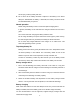
Frequency Chart Model: Serial Number: CH Rx Freq Rx CTC/DCS Rx Signal Tx Freq Tx CTC/DCS Signal Type Signal Comb. Band Width 1 2 3 4 5 6 7 8 9 10 11 12 13 14 15 16 We endeavor to achieve the accuracy and completeness of this manual, but no warranty of accuracy or reliability is given. All the above specifications and design are subject to change without notice due to continuous development.