INSTALLATION AND OPERATING INSTRUCTIONS Air curtains C1, D2 04/2013
Air curtains Contents Application, Operating Conditions and Construction..............................................................3 Designations, storage, shipping.................................................................................................4 Installation.....................................................................................................................................5 Dimensions.........................................................................................
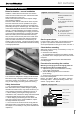
Air curtains Application, Operating Conditions and Construction Information from the manufacturer DoorMaster door curtains are manufactured in compliance with the valid Czech and European technical regulations and technical standards.
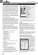
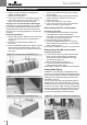
Air curtains Designation, Storage and Dispatch The covering sidewalls are laminated. The intake panel has an integrated filter insert (G1). The exhaust chamber is furnished with anti-noise insulation. The exhaust screen is adjustable. As standard D2 curtains are equipped with 3-speed fans made by leading european manufacturer. The D2 curtains are equipped with fan units from the leading manufacturer of fans, Nicotra, and in the standard version, they have a three-step speed control.
Air curtains Installation, mounting Rules for location - correct installation Install the curtains above the entrance door with the outlet slot near the side of the door and with the intake side in the direction of the room. Observe the instructions listed in the chapter "Usage and operating conditions". Place the curtain with the outlet slot as close as possible to the wall and as close as possible to the upper edge of the door opening so that air is prevented from penetrating through an unwanted gap.
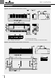
Air curtains Dimensions Figure 6 - dimensions of the curtains in the C1 series * ** Size A ZAV – Hanging on hanging profile NKC – Hanging on wall console * W: curtain with water heating ** E1, E2: curtain with el.
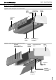
Air curtains Arrangements Figure 8 – basic description of C1 series curtain cover for the wiring connections for the media plastic sidewall removable intake panel adjustable outlet screen terminals for the electrical connection Figure 9 – basic description of D2 series curtain removable intake panel with integrated filter insert internal aluminum sidewall connections for the media plastic sidewall adjustable outlet screen terminals for the electrical connection service panel that can be opened 7
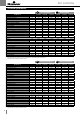
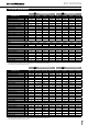
Air curtains Technical parameters N DoorMaster C1 Low-temperature W Water heating C1-N-100 C1-N-150 C1-N-200 C1-W-100 C1-W-150 C1-W-200 Door width (max.) mm 1.000 1.500 2.000 1.000 1.500 2.000 Total width of curtain mm 1.040 1.540 2.040 1.040 1.540 2.040 Height of curtain body mm 240 240 240 240 240 240 Depth of curtain body mm 365 365 365 365 365 365 kg 23 / 24,5 30,5 / 32 39 / 40,5 25 / 26 33,5 / 34,5 44 / 46 m³/h 1.200 1.800 2.400 1.100 1.600 2.
Air curtains Technical parameters N DoorMaster D2 W Low-temperature Water heating D2-N-100 D2-N-150 D2-N-200 D2-N-250 D2-W-100 D2-W-150 D2-W-200 Door width (max.) mm 1.000 1.500 2.000 2.500 1.000 1.500 2.000 D2-W-250 2.500 Total width of curtain mm 1.020 1.520 2.020 2.520 1.020 1.520 2.020 2.520 Height of curtain body mm 340 340 340 340 340 340 340 340 Depth of curtain body mm 700 700 700 700 700 700 700 700 Weight (1-speed / 3-speed) Airflow (max.
Air curtains Installation, Media Connection Raise the curtain and slide the hanging profile between the binding washers. Tighten the nuts (counter). Carry out the connection of the media (see page 11). Carry out the connection of the control and main lead-in for the electric power (see page 12).
Air curtains Wiring and Commissioning Using flexible stainless hoses is the easiest way to connect the water heat exchanger to the heating water distribution piping; these hoses can be ordered as optional accessories (G 3/4"-250 hose; max. operating pressure 1MPa). Insert a shut-off valve in the air curtain connecting place to the heating water circuit. The inlet and outlet line must also be equipped with air-venting valves to enable exchanger venting.
Air curtains Wiring and Commissioning As standard, the DoorMaster COMFORT air curtains are designed to be controlled by remote (external) controllers; therefore, no controls are situated on the air curtain casing. For the number of speed and heating stages, and control features, refer to table 9, page 21. External controllers (switches) must be dimensioned at least for the minimum inductive load; for values of inductive load, refer to the applicable tables further in the respective tables on pages 12-13.
Air curtains Accessory Installation stat 80°C, operation thermostat 60°C) is forbidden. It is forbidden to operate the electric heater without the outlet air temperature control and without ensuring a steady flow of transported air. Checking during the First Air curtain Start-Up During test operation, check the air curtain for unusual noises (squeaking, resonance, etc.), excessive vibrations or the smell of burning insulation. The testing operation must last at least 30 minutes.
Air curtains Accessory Installation Figure 16 – Thermo-valve sensor installation, C1 Figure 17 – Thermo-valve sensor installation, D2 TVW-P (optional accessory) Thermostat sensor Thermostat capillary tube Sensor holder + 2.9x9.5 (2x) DIN 7971 + 3.5x6.5 (2x) DIN 7971 (TVW-P accessory) Rubber grommet (part of the product) Internal longitudinal profile (part of the product) Air-venting valve (not included in the delivery) Rubber grommet (black) Sensor holder + 2.
Air curtains Controllers and Room Thermostats Figure 19 – Fan speed controller RAB 91 Three-stage fan speed controller Application: - C1 air curtains …/TR (with transformer) - D2 air curtains, all versions Control: The controller's switch enables three-stage fan speed (air flow rate) control.
Air curtains Wiring diagrams Figure 22 – C1-E1 air curtains connection X1 - Main power connection (supply) L1+L2+L3+N+PE - Input voltage terminals TK-TK - under-voltage circuit breaker connection terminals DK1-DK2 - Door contact connection terminals LV+Q3 - Two-pole switch/breaker connection terminals LE+Q1E - Electric heater controller power supply terminals XS - Terminals for air curtain chaining (assembly according to the type), refer to the "Air Curtain Chaining" section page 21) Figure 23 – C1-E1/TR a
Air curtains Wiring diagrams Figure 24 – C1-E2 air curtains connection X1 - Main power connection (supply) L1+L2+L3+N+PE - Input voltage terminals TK-TK - under-voltage circuit breaker connection terminals DK1-DK2 - Door contact connection terminals LV+Q3 - Two-pole switch/breaker connection terminals Electric heater controller power supply terminals: Q1E - I. Electric heater section Q2E - II. Electric heater section Q3E - I.+II.
Air curtains Wiring diagrams Figure 26 – C1-W and C1-N air curtains connection X1 - Main power connection (supply) L+N+PE - Input voltage terminals DK1-DK2 - Door contact connection terminals LV+Q3 - Fan controller connection terminals: STA21 + VVI 46.20 - TVW-E thermo-electric valve Figure 27 – -W and C1-N /TR air curtains connection X1 - Main power connection (supply) L+N+PE - Input voltage terminals DK1-DK2 - Door contact connection terminals Fan controller connection terminals Q1 - 1.
Air curtains Wiring diagrams Figure 28 – D2-E1 and D2-E2 air curtains connection Figure 28 - D2-E1 and D2-E2 air curtains connection X1 - Main power connection (supply) L1+L2+L3+N+PE - Input voltage terminals TK-TK - under-voltage circuit breaker connection terminals DK-DK - Door contact connection terminals XV - Fan controller connection terminals Q1 - 1. Speed stage Q2 - 2. Speed stage Q3 - 3.
Air curtains Wiring diagrams Figure 30 – control of chained C1 air curtains using an internal switch Q1 - 1. Speed stage Q2 - 2. Speed stage Q3 - 3.
Air curtains Air Curtain Chaining Observing all instructions of the Installation Instructions Manual, suspension dimensioning and instructions for electrical wiring, the air curtains can be chained into any configuration (of the same air curtain line and type of heating), and thus can cover wider door openings.
Air curtains Operating and Maintenance Instructions Figure 32 – Mechanical connection points Join nearby air-curtains using connection holes – DM SS D2 connection set. Figure 33 – Mechanical connection points, D2 D29 side hole connection holes for curtain chaining D2 Air Curtain Chaining Mechanical Connection The air curtains can be connected to create a visually non-disturbing assembly. Connection can be carried out using a connection kit (DM SS CD2 accessory).
Air curtains Maintenance and Screening Checks Screening Checks and Maintenance DoorMaster air curtains are made of high quality components; therefore, they do not need special maintenance. It is only recommended to perform regular service checks (every six months of operation) which include removal (vacuuming) of dust deposits from the air curtain interior, filter and heat-exchanging surfaces of the exchangers (blowing or vacuuming), if equipped.
Air curtains Náhradní díly, servis Troubleshooting The heat-exchanging surface of the exchanger can be vacuumed or blown through. To remove deeper dirt, use a long bristle brush. Be careful not to damage the exchanger fins! If distorted, the exchanger fins can be repaired using a flat screwdriver or a special comb (3.2 mm). Cleaning the Air Curtain Interior and Checking the Internal Parts This applies for the air curtain interior, water heat exchanger leak check, screw and electrical connection checks.
Air curtains Spare parts, service and disposal Check procedure: Verify the air curtain control possibilities, refer to table #9 on page 20. Using a resistor, check the closing of the corresponding contacts in the controller/sensor/door contact. The air curtain functionality can be verified by interconnecting the corresponding terminals inside the air curtain.
Air curtains Further, applicable national regulations and directives must be observed. Printing and language mistakes are reserved. These Installation and Operating Instructions (as a whole or a part) must not be printed or copied without prior written permission from REMAK a. s., Zuberská 2601, Rožnov pod Radhoštěm. These Installation and Operating Instructions are the sole property of REMAK a. s. Changes reserved.
Air curtains 27
Výrobce si vyhrazuje právo změny bez předchozího upozornění. R08031101 REMAK a.s. Zuberská 2601, 756 61 Rožnov pod Radhoštěm, tel.: +420 571 877 878, fax: +420 571 877 877, email: remak@remak.cz, internet: www.remak.