
Service manual


57
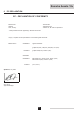
8.2 The boiler components
1
2
3
4
5
6
8
7
9
10
11
59970LTGBW7H045a
59970LTGBW7H045
1. Flue / Air inlet connection
2. Flue gas measuring point
3. Heat exchanger
4. Front plate heat exchanger
5. Syphon
6. Control panel
7. Fan
8. Air inlet tube
9. Gas valve multiblock / Ignition transformer
10. Ignition/ionization electrode
11. Control unit
8.3 Working principle
The Remeha Avanta 18v casing serves as a sealed air box,
with air drawn in by the fan. On the outlet side of the fan is
a venturi, into which a measured quantity of gas is injected
based on the volume of air available. The fan speed con-
trol is dependent on the settings of the external control, the
advanced boiler controller ‘abc
®
’ and the prevailing tempera-
tures (measured by the temperature sensors).
This method of gas/air ratio control ensures that the gas
quantity is precisely adjusted to the air quantity. Thus creating
optimum combustion over the whole heat input range. The gas
and air is mixed in the venturi and then passes into the spe-
cially designed pre-mix burner. After combustion, the hot flue
gas is directed through a specially designed, high efficiency
helicoil stainless steel heat exchanger with a large surface
area, and transfers its heat to the system water circulating
around the coils. In the condensing part of the exchanger the
water vapour in the flue gas condense within it and the heat
released during this process (the so-called latent or condens-
ing heat) is also transferred to the system water. The conden-
sate water so formed is discharged from the heat exchanger
via a siphon.
In normal operation, the boiler’s flue gas discharge will pro
duce a visible white condensing “plume” and therefore care
should be taken when choosing a location for the terminal.
8.3.1 Regulating
The Remeha Avanta 18v is a fully modulating boiler and can
be regulated using one or more of the following methods;
1. Open Therm – 2 wire interface compatible with the Remeha
Celcia 15 room compensator and the Remeha Celcia 20
outside weather compensator or with any other proprietor’s
OpenTherm
®
controls.
2. Open Therm thermostat in combination with an external
time clock.
3. On/Off room thermostat – volt free (on the X9 terminal
strip).
4. On/Off room thermostat – 230 V (on the X2 terminal strip).
5. 230 V Switching time clock – compatible with the Remeha
two channel time clock or with any other appropriate time
clock. For further details see par. 2.8.