
Technical data

35
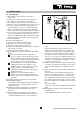
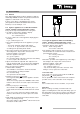
11. FAULT-FINDING
11.1 General
This chapter differentiates between appliances with the
modulating
rematic
®
weather-compensated control and
appliances controlled in some other way.
In those cases where a modulating room control
(Honeywell Chronotherm Modulation with relevant
interface) is used, follow par. 11.2.
11.2 Faults in appliances in combination with the
rematic
®
weather-compensated boiler control
Carry out the steps listed below in the order given:
1. No figures appear in the appliance display.
Check: - the mains voltage 240 V
- the control box fuses
2. Is there a fault code on the appliance display (figures
flashing)?
If yes, continue at par. 11.4.
3. Check the operating mode of the appliance
(see par.
6.4.2)
.
- ‘0’ (no heat demand): continue with point 4.
- ‘1’ to ‘9’, ‘H’, ‘L’: try to find the cause of the fault,
according to the operating mode shown.
4. Check the operation of the appliance by connecting a
wire bridge to the 16-pole wire connector X15
between terminals 1 and 2 (B1).
Does the appliance start up?
Yes, go on to point 5.
No, check the wiring of the wire connector. If the wiring
is correct, replace the control box.
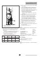
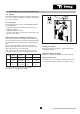
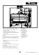
5. Open the instrument cupboard. This cupboard con-
tains an interface PCB
(see fig. 23)
for the modulating
rematic
®
control. The PCB also includes two LEDs.
There are now four possibilities:
1. Neither LED is flashing:
Check whether connections L and N of the PCB
(screw clamp X1) are being fed 230V.
No: check the wiring.
Yes: replace the interface PCB.
2. LED B
(see fig. 23)
is not flashing.
First check the wiring between the appliance and the
rematic
®
control.
Then, if necessary, replace the
rematic
®
control. If the
fault has still not been corrected, replace the interface
PCB.
3. LED A
(see fig. 23)
is not flashing:
Check whether the tape cable connector (X7) is cor-
rectly mounted in the interface PCB and in the control
box.
Then, if necessary, replace the interface PCB. If the
fault has still not been corrected, replace the control
box.
4. Both LEDS are flashing. This indicates that the instal-
lation is operating correctly.
Check the settings of the
rematic
®
control. Refer to the
instructions for the control.
Fig. 23 Interface PCB for modulating rematic
®
control
11.3 Faults in appliances without a modulating
rematic
®
weather-compensated boiler control
In the event of faults the following situations may occur:
1.No figures appear on the display.
Check: - mains voltage 240V
- fuses in the control box.
2.The appliance will not start up (no error message):
Check whether the room thermostat or weather-com-
pensated boiler control:
- are correctly connected
- are correctly set
- are faulty.
3.Check the operation of the appliance by connecting a
wire bridge to the 16-pole wire connector X15
between terminals 1 and 2 (B1).
Does the appliance start up?
- Yes, continue at par. 11.4
- No, check the wiring of the wire connector. If the
wiring is correct, replace the control box.
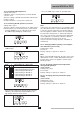
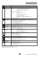
11.4 Fault codes
In the event of an error message, both the 'code' dis-
play and the ' ' display will flash.
For an explanation of the various fault codes and their
possible causes, refer to the table on the next page.
Note:
For a readout of the most recent faults, see par. 6.4.8.
Important:
Before resetting, accurately record the fault code
(figures, including flashes and dots) and always pass on
this information if you request assistance. The fault code
is important for correctly and rapidly tracing the nature
of the fault.