
Technical information


Remeha Quinta 85
18
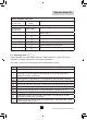
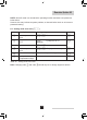
service engineer level only:
Speed mode,
see Par. 6.8
alternate half
digit <
Fan speed
Failure mode,
see Par. 6.9
flashing digit
1
Failure code
2
Operating code during failure
3
Flow temperature during failure
4
Return temperature during failure
5
DHW temperature during failure
6
n/a
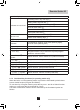
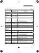
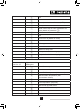
Table 03 Flow diagram control system
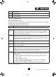
6.3 Operating mode (x[[)
During operation the code-display shows the status (position in cycle) of the boiler,
whilst the t-display indicates the actual flow temperature.
The digits or letters in the code-display have the following meaning:
Code Description
0
Standby: there is no heat demand from control system.
1
Pre-purge: before start-up, the boiler is purged for 4.2 seconds.
Post-purge: when the heat demand has been met, the fan continues to
operate for another 10 seconds.
2
Ignition: ignition is activated for 2.4 seconds while the gas valve is opened.
3
HTG mode; the boiler operates in the HTG mode.
4
DHW mode: the three way valve or DHW pump activated (Broag priority only)
5
Internal check
6
Normal control stop during HTG (flow temperature > set point + 5 °C)
7
HTG pump run on
8
DHW pump run on or for three way valve option, HTG pump run on with
valve open to DHW (max. 5 minutes)
9
Normal control stop during DHW (flow temperature > set point DHW + DHW
control stop set point + 5°C)