
User`s manual


DIGITAL AND OPTO PORTS SECTION 6
Page 6-2 RPC-320
ground through a 10K/100K resistor packs using jumper
W7. 10K is on digital port A only.
Jumper W7 for pull up or down configuration is as
follows:
W7[1-2] Pull up
W7[2-3] Pull down
Setting W7 for pull up makes interfacing to switches and
"open collector" TTL devices easy . See "Inter facing to
Switches and other devices" below.
Digital Port P6
Connector P6 has 8 digital I/O lines for general pur pose
use. Additionally, 3 ground and a + 5V positions are
provided. + 5V power and gr ound may be brought in or
taken from this connector. Lines are numbered L0-L7.
This port may be used to interface switches, dr ive small
LED' s, and provide general purpose TTL I/O to other
logic devices. Voltage and current param eters are the
same as J3 except there is no high current output. Port
C from an 82C55 is used for this I/O.
Upon power up or reset lines L0 to L3 are inputs while
L4 to L7 are outputs. Lines L4 and L5 are low while L6
and L7 are high at power up. All lines are connected to
a 10K pull up resistor (R21). Lines are reconfigured for
all inputs or outputs using the CONFIG LINE 0
command, found in Appendix A.
High Current Port L8
L8 will switch 2 amperes to ground through a "zero
ohm" FET switch. Maxim um off vo ltage is + 50 volts
DC. "ON" resistance is about 0.5 ohm.
Use this port to switch LED back lighting for LCD
displays on or off under softwar e control.
This line is always an output. Use the LINE 8 com mand
to turn this line off or on.
LINE 8,ON
LINE 8,1 Both commands turn on L8.
The F ET sw itch is rated for much higher curr ent.
However, continuous current is much less without a heat
sink attached. You may draw more than the rated 2
amps on an intermittent basis. How m uch and for how
long depends upon your application. A quick way to
check for excessive current is to touch (VERY
CAREFUL LY!) Q2 (next to P2). It can be warm to hot
to the touch. Consider the maximum ambient
temper ature the b oard w ill operate at. At 70°C, warm to
the touch at room temperature m ay be too much.
Consider adding a heat sink.
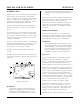
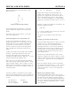
The PW M com mand m ay be used with this port. Use
the circuit in Figure 6-2 when switching inductive loads.
Use the "GN D" ter minal next to L8 when switching
loads.
Optically Isolated Input
ISOA and ISOB ar e inputs to an optica l isolator. This
input is read as L8. It can also generate an interrupt
provided W8[1-2] is jumpered and ONITR is set. Refer
to Chapter 12 for input voltage and interrupt
requirements. This line can be used to "wake up" the
CPU from low power IDLE 2 mode.
The status is read using the LINE(8) function.
A = LINE(8)
A 1 is returned when there is no input and a 0 when
voltage is sufficiently high enough to turn on the isolator
(about 3.5 volts).
The opto isolator is not polarity sensitive. This input can
be used in conjunction with or independently of the
ONIT R statement.
Digital I/O Commands
The CONFIG LINE statement is used to configure lines
at J3 and P6 for inputs and outputs. J3 power up default
is all inputs. P6 power up default is L0 to L 3 are inpu ts
and L4 to L7 are outputs. CONFIG LINE 0 refers to P6
while CONFIG LIN E 100 to J3.
The L INE comm and has 3 variations: LIN E, LINE B,
and LINE #. Each is described below. See Appendix A
for more inform ation.
LINE function and statement is used with M PS-XX opto
rack at J3. It accesses a module according to the
position number printed on the MPS board. Lines are
numbered from 100 to 123. The opto module number
used in this command is computed by adding 100 to the
board position number. LINE also accesses L0-L8 on
P2 and P6.
The LIN E B function and statement is used to access