XTR39 Hand-Held LCD Remote Control Installation Instructions -1-
INTRODUCTION ..................................................................................................................................4 XTR39 Overview......................................................................................................................................................................................4 XTR39 Features ..........................................................................................................................................................
Built-In IR Code Library ......................................................................................................................................................................22 Testing IR Commands in the IR Library ............................................................................................................................................23 Learning IR Commands (XIR2)..............................................................................................................
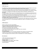
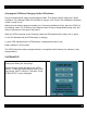
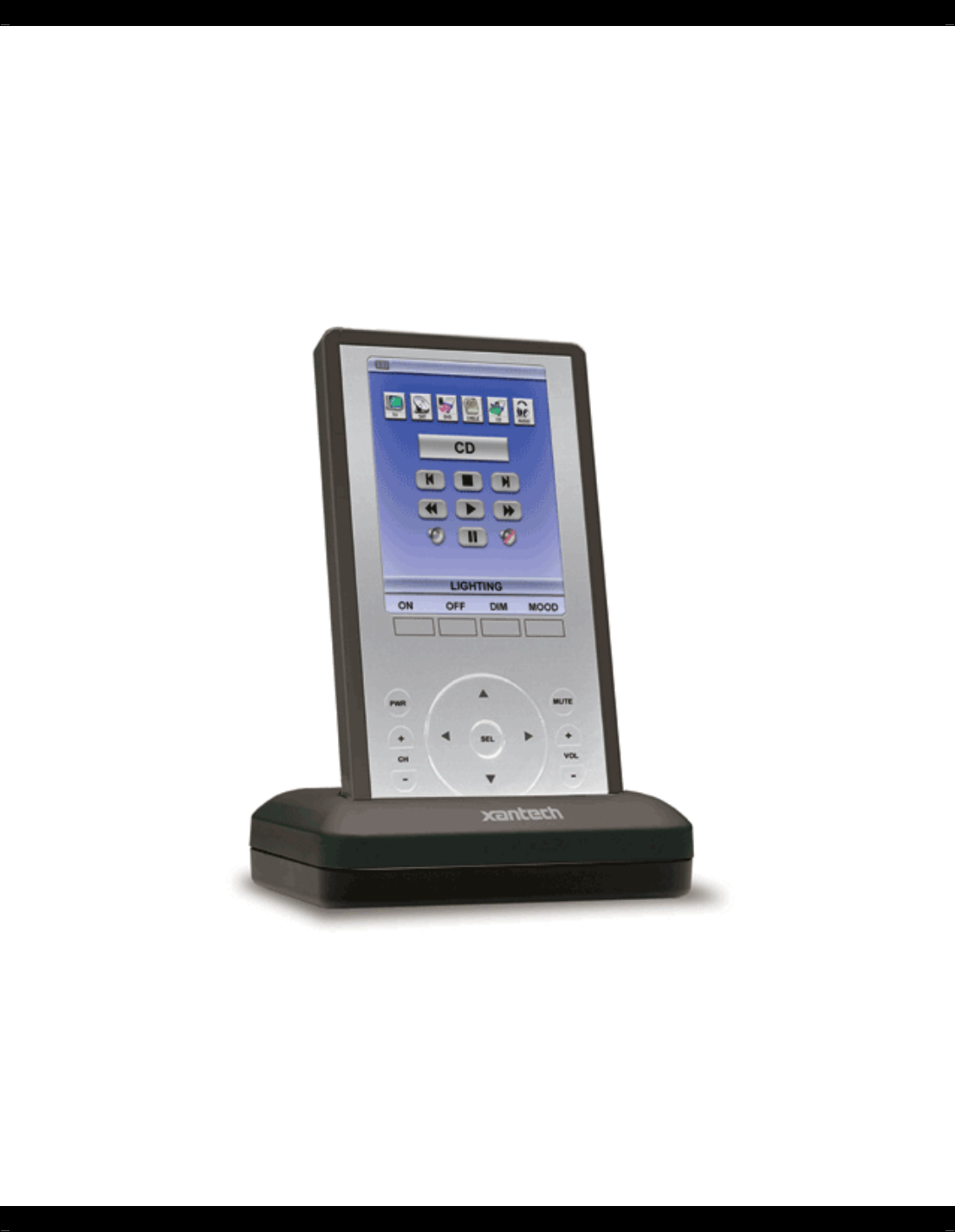
INTRODUCTION XTR39 Overview The XTR39 Color LCD touch-screen remote control from Xantech is the perfect solution to the clutter of difficult-to-use remote controls that accompany most home theater systems. The XTR39 is a stylish, simple-to-use remote control that can be personalized via its vivid full color 3.
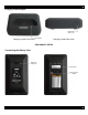
XTR39 Diagram XTR39 Front View Note: Simulated graphics.
Charging Cradle Diagram Charging Cradle Front View Charging Cradle Rear View PRELIMINARY SETUP Connecting the Battery Pack -6-
Charging the XTR39 and Charging Cradle LED Indicator Plug the included power supply into the charging cradle. Then plug the power supply into a power receptacle. The Charging Cradle LED will blink an ‘orange’ color 3 times. This indicates the Charging Cradle is ready for use. Making sure the battery has been installed (see ‘Connecting the Battery Pack’), place the XTR39 on the charging cradle. The XTR39 must be charged at least 10 hours straight without being used.
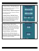
(1) Display Settings - Backlight Adjustment Touch and drag the slider to adjust the XTR39 to a desired backlight brightness level. (2) Display Settings - Brightness Adjustment Touch and drag the slider to adjust the XTR39 to a desired brightness level. (3) Display Settings - Backlight Timeout Select the list box and select the desired backlight timeout. This determines the amount of time, in seconds, when the backlight will turn off after the XTR39 is no longer is use.
(1) System Information The XTR39 can display the firmware version and project information. The top displays the system firmware version. The bottom displays the IR library version. Touch-screen Calibration Adjustment The accuracy of triggering a Hot-Spot associated to a GTL (Graphical Touch-Link) can be calibrated. It is advised to use a PDA stylus for increased precision. From the “XTR39 Setup” page, press the down-arrow to enter calibration adjustment mode.
PROGRAMMING SETUP Universal Dragon™ Installation Guide This guide provides users with step by step instructions on how to install the Universal Dragon™ software. Requirements: -1.0 GHz or greater processor (CPU) -Windows 2000 and Windows XP -650 MB Hard Drive space (you will need more as your libraries and projects expand) -256 MB RAM (512MB preferred) -Mouse, Keyboard, USB port The new Universal Dragon™ software requires the latest ‘.
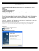
Note: If you do not have the .NET or Microsoft InstallShield update on your computer, this will get installed first. 3. Click on the Next button: 4. Enter your name and company and select if the installation should only be available to you or to anyone else who may log into your computer, then click Next: 5. The default installation path for Universal Dragon™ is ‘C:\Program Files\Xantech\Universal Dragon\’, if this is acceptable click Next.
6. The installation will proceed showing the user the current Status: 7. After installation is complete. Click on the Finish button.
8. The installation package will ask you to reboot your computer. Click Yes so that the installation process can be completed: 9. After your computer reboots, the installation package will check to make sure that you have the latest version of Universal Dragon™ on your computer. 10. You can now run the Universal Dragon™ software by double clicking the shortcut on your desktop: Or selecting Universal Dragon™ from your start menu under the Xantech start folder.
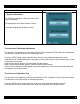
INSTALLING AND CONFIGURING THE Universal Dragon™ SOFTWARE Connecting the XTR39 to the PC To program the XTR39, the unit will need to be connected to a PC. USB Connection Open the access cover on the XTR39 and pivot the cover down. Connect the wide end of the included USB cable to the USB port of your PC and the small end to the connector on the front panel of the XTR39. NOTE: The USB connection requires a ‘B’ Type connector to interface with the XTR39. USB cable is included with the XTR39.
Configuring USB Port To configure the USB Port for the first time, complete the following instructions: A New Hardware window should appear on the PC. Follow the instructions that follow and allow Windows to select the proper driver. Note: If the Driver is not found, follow the steps below: If the USB Driver is not found, select “Include this location” when Windows prompts you for where to look for the driver. Click on BROWSE and point windows to C:\Program Files\Xantech\Universal Dragon\USB .
STARTING A PROJECT With the Universal Dragon™ software open and the COM PORT communication verified proceed as follows: From the File menu choose “NEW PROJECT” (CTL+N) or choose “OPEN PROJECT” (CTL+O) to modify an existing project file. You may also use the NEW PROJECT or OPEN PROJECT icons located on the Tool Bar at the top of the page. In the New Project window, type a file name such as “Theater Room” and click “SAVE”. The proper file extension is added automatically. A new window will appear.
CREATING THE GRAPHICAL USER INTERFACE (GUI) Through Universal Dragon™ software, you can easily create stylish and intuitive screens in multiple pages for controlling any IR Device. Once a project is created and a setup environment chosen, you are automatically placed in Graphics mode and are now ready to create your GUI (Graphical User Interface) screen.
Choosing A Style Multiple STYLES of Backgrounds, Source Buttons, and Function Buttons are included in a graphics library within the software. Each STYLE contains its own set of Backgrounds and GTL’s (Graphical Touch Links). Once a STYLE is selected, only its associated Backgrounds, Source buttons and Function Buttons (GTL’s) will be available. Backgrounds To choose a style: 1) Make sure you are in Graphics Mode. If not, click on the Graphics TAB in the XTR39 window.
2) 3) 4) Selected state. The UP and DOWN graphics can be edited. Please see Editing GTL Properties for more information on this. Click on the Buttons TAB in the GRAPHICS window. All of the Function Buttons associated with that Style will be displayed. Select a Button and drag-and-drop it anywhere on the Background in the XTR39 Systems window. If a desired Function Button is not shown in the list, simply select a BLANK button and drag it onto the Background.
Inserting Additional Pages for a Single Source Additional blank pages can be inserted for a given source. After a blank page is inserted, it may be populated with Function Buttons just as in the previous section. This may be useful either when a page becomes full of commands or for easier operation (i.e. separating the Motion Control buttons and Menu Navigation Buttons of a DVD Player on separate pages). The Blank Page is always inserted AFTER the current page you are inserting from.
Editing GTL Properties Properties of a GTL button can be edited for Text, Font and color. This allows the user to drag a blank GTL button on to the GUI page and edited it to their liking. Each GTL has two states a Down and an Up state. Each of these states can be edited separately to give a unique appearance when either selected or non-selected. To edit a GTL proceed as follows: 1) Right-click on the GTL to be edited. Note: Existing TEXT on a GTL cannot be changed or edited.
Inserting Labels A Label may be inserted anywhere on the GUI screen to give more detailed description to a GTL or a group of GTL’s. The label may even be used as a Function GTL or even as a Source GTL if so desired. To insert a Label proceed as follows: 1) Right-Click on any blank area (no GTL’s) in the XTR39 Systems window. 2) From the Drop-Down menu, select whether this will be a text Label, text-only Source Button, or a text-only Function Button.
Testing IR Commands in the IR Library Once you have located all of the Command Group codes for the appropriate Manufacturer/Component, you will need to test the commands to see which Command Group is associated with your specific component. NOTE: To test commands out of the Library, the PC running Universal Dragon™ software must be connected to the XTR39 via the USB programming port. With the Manufacturer and Component expanded and the proper library selected.
entitled Placing Commands onto the GTL’s. If no working commands can be found in the IR Library, please proceed to the following section entitled Learning IR Commands. Learning IR Commands (XIR2) An IR Learning Eye is located on the front of the XTR39. Note: Commands learned through the XTR39 front learning eye (XIR2 method) are NOT backwards compatible to other Xantech devices (i.e. MRC44/88, URC-2 etc…).
7) Select the command the left side of the Palette Editor (i.e. Power, Play, Stop etc.). A message stating “Waiting to receive IR” will appear 8) While continuing to keep the source remote within 1” from the IR learning eye, press and release the corresponding command button on the source remote. A symbol ( ) will appear to the left of the selected function indicating that an IR code has been learned. Note: If you wait longer than ten seconds, a time-out message will appear.
Editing Function Names in the Palette Editor If a function displayed on the Source Components Remote is not displayed in the function list on the left hand side of the Palette Editor window, you can either RENAME an existing function or ADD a new function to the list. Editing function names in the Palette Editor will only effect the Palette File you are currently saving to (i.e. Making a change to a function under DENON DVD will only appear in DENON DVD).
Creating a Palette File A Palette File is a file of learned commands that is ready to be placed under a GTL for use in the XTR39. Note: As previously mentioned, Palette files created in Universal Dragon™ software (XIR2 method) cannot be used with other devices. 1. 2. Select to create a new palette file. Then choose to either add a new brand or component (to all brands).
Selecting IR Palettes Scroll the list (if necessary) and click on the component of each palette you need for your system (i.e. Pioneer CD, RCA DSS, etc). As you click on each file name, the palettes will appear side-by-side, left to right, with the filename in each title bar. NOTE 1: The various palettes and window boxes can be moved and sized (except the virtual keypads) for ease of use.
Testing Commands Placed on the virtual XTR39 Window Commands placed under buttons in the virtual XTR39 window may be tested prior to downloading. To test commands, the PC must be connected to the XTR39 and the XTR39 must be pointed at the source to be controlled. In Universal Dragon, under the menu items, change from Normal Mode to Test Mode. Select the appropriate GTL button in the XTR39 window with the IR codes placed under it to test. (i.e. PLAY button). The button should now appear selected.
MAINTENANCE Firmware Update To access the latest firmware updates, proceed to www.xantech.com and download the latest file. Place the downloaded file in an easy to locate directory. 1) 2) 3) Launch Universal Dragon and connect the XTR39 to the computer via the USB port. Go to menu item “Base Unit”. Then select “Upgrade Firmware” and then “XTR39”. A new window will appear. Select the firmware version to be updated. Cleaning the XTR39 For safety reasons, disconnect the battery before cleaning.
FCC NOTICE * Section 15.19 Labeling requirements This device complies with part 15 of the FCC rules. Operation is subject to the following two conditions: (1) This device may not cause harmful interference and (2) This device must accept any interference received, including interference that may cause undesired operation. * Section 15.21 Information to user The changes or modifications not expressly approved by the party responsible for compliance could void the user’s authority to operate the equipment.
ACCESSORY ITEMS Xantech offers the following accessory items for the XTR39: XTR39BTRY. Lithium-Ion battery for the XTR39. XTR39CRDL. Cradle and power supply for the XTR39. WARRANTY INFORMATION REPAIRS: TECHNICAL SUPPORT PRE-AUTHORIZATION Certain products require a Pre-Authorization from our Technical Support Department prior to a Return Authorization (RA) being issued. Please call our Technical Support Department at 800 843-5465 Extension 301.