ZTS-100 (Z-Thermostat) 1
Table of Contents Introduction .................................................................... 3 Features list ............................................................... 3 Glossary .......................................................................... 5 Physical Installation and Wiring .................................... 6 Installation Location .................................................... 6 Wiring .......................................................................
ZTS-100 Z-Thermostat Introduction Welcome to the Z-Wave world of home automation, your ZTS-100 Z-Thermostat (Figure 1) is a comfort control master that allows to control your room temperature with programmable time schedule WAKE, AWAY, HOME and SLEEP event which can maximize energy conservation and comfort while minimizing the effort required to maintain the appropriate temperature in your home whether you are at home or away.
Heat Pump change over valve: z Selectable change over with cool or with heat Power: z Powered by alkaline batteries AA x 4pcs or 24Vac Program Style: z 2 program modes for scheduling (Mo-Fr, Sa-Su) z 4 Separate Time and Temperature Settings for each program z Heat and Cool set-points for each program z Temporary Program Override z Permanent Program Override z Built-in flash memory stores heat and cool program settings Temperature Display and Control: z Temperature display in °F or °C z Te
Glossary Devices and nodes are all terms to describe an individual Z-Wave Device or Node device. These are all interchangeable when setting up your Z-Wave network. Inclusion Add a Z-Wave device to the network. Exclusion Delete a Z-Wave device from the network. Remove To take a device out of a group, scene or association group while that device still exists in the same Z-Wave network.
Physical Installation and Wiring L CAUTION − Read the enclosed instructions carefully before installing your new Z-Thermostat. Pay close attention to all warnings and notes and carefully follow the installation steps in the order they are presented to save time and minimize the risk of damaging the thermostat or the system it controls. − Turn off ZTS-100 and the electronic devices (e.g. heater, cooler) which will be connected and the electric source before installation and maintenance.
Important! The ZTS-100 can be powered by alkaline batteries AA x 4pcs or 24Vac. Connect the “24Vac Common” (typically the black wire/terminal) and “24Vac Power” (typically the Red wire/terminal) from the HVAC system to the ZTS-100 HVAC System terminal block “C” and “RH” or “RC” terminals (the RH and RC terminals are default tied together). Common or Split Transformer Systems: Most HVAC systems have a common heating and cooling transformer.
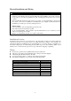
Jumper settings for ELECTH-HPUMP and HE-HG: Jumper Function Description Set to ELECTH for non heat pump system Set to HPUMP for heat pump system Set to HG for Gas heat-fan controlled unit Set to HE for Electrical heat-fan controlled unit 8
Mounting: 1. 2. 3. 4. 5. 6. 7. 8.
ZTS-100 Z-Thermostat Operations The following section will guide you through the set up processes for your ZTS-100. Different listening nodes are able to act as repeaters to enlarge the network range. Please note that all Z-Wave thermostat controllers are designed and manufactured by various vendors whom are compatible with your ZTS-100 as long as they carry the Z-Wave logo: (Please carefully read through the following then store the manual for future reference.
Normal Operation Mode Change Operation mode Note 1: In Heat mode => it displays “HEAT” if ELECTH is selected. => it displays “HEAT PUMP” if HPUMP is selected.
Select Fan mode Step Procedure / Description LCD indication Press “Fan” key once to change the Fan mode: FAN AUTO -> FAN ON 1 FAN AUTO: Electric heat (HE): Fan runs only when Heating/Cooling is running. Gas heat (HG): Fan runs only when Cooling is running. Press “Fan” key once to change the Fan mode: 2 FAN ON: Fan stays on all the time.
Press “Prog” key once to select PROG mode: PERMANENT OVERRIDE: 3 Permanent override the schedule until user change back to “PROG ON”. Override/Permanent Override Note 1: Override/Permanent Override is only available in HEAT, COOL or AUTO mode. Step Procedure / Description LCD indication Press “Prog” key once to select PROG mode: OVERRIDE or PERMANENT OVERRIDE at 1 Home page. Press Up/Down key to adjust set point temperature in HEAT or COOL mode. Press “Prog” key once to confirm the setting.
In AUTO mode, user needs to set heat and cool set points temperature. 3 Press Up/Down key to adjust auto heat set point temperature in AUTO HEAT mode. Press “Prog” key once to confirm the setting. Press Up/Down key to adjust auto cool set point temperature in AUTO COOL mode. 4 Press “Prog” key once to confirm the setting and back to Home page. Setting Mode (set Day, Clock, 12/24 hour, F/C, Swing and Diff.
Setting mode: Step Procedure / Description LCD indication Press and hold “Mode” key for 2 seconds to entry the setting mode. 1 Day will keep flashing, press Up/Down key to set day from MO-SU. Press “Prog" key once to confirm the setting and it will go to hour setting. 2 Hour will keep flashing, press Up/Down key to set hour. Press “Prog" key once to confirm the setting and it will go to minutes setting. 3 Minutes will keep flashing, press Up/Down key to set minutes.
Press “Prog" key once to confirm the setting and it will go to temperature F -> C selection. Press Up/Down key to toggle the temperature F -> C selection. ⇓ 5 Press “Prog" key once to confirm the setting and it will go to swing setting. 6 Press Up/Down key to set the swing setting. (Range is from 0.5oC to 2oC or 1oF to 4oF ) Press “Prog" key once to confirm the setting and it will go to differential set point setting. 7 Press Up/Down key to set the differential set point setting. (Range is from 0.
Press “Prog" key once to confirm the setting and it will go to the Home page.
Press “Prog" key once to confirm the setting and it will go to event mode. Press Up/Down key to select the event (WAKE -> AWAY -> HOME ⇓ -> SLEEP). ⇓ 2 ⇓ Press “Prog" key once to confirm the setting and it will go to hour setting. 3 Hour will keep flashing, press Up/Down key to set hour. Press “Prog" key once to confirm the setting and it will go to minutes setting. 4 Minutes will keep flashing, press Up/Down key to set minutes.
Press and hold “UP” and “DOWN” key for 2 seconds to disable / enable event during the time setting. If the event is disabled, “OFF” will 5 ⇓ be displayed. If the event is enabled, time will be displayed and Hour will keep flashing. Press “Prog" key once to confirm the setting and it will go to target setting. If the event is enabled, it will go to target setting. 6 Target will keep flashing, press Up/Down key to adjust Heat set point for heating.
Z-Wave Add (Inclusion) / Delete (Exclusion) Mode Symbol Inclusion and Exclusion Mode Key Description N/A N/A N/A N/A Add (Inclusion) / Delete (Exclusion) Back to Home Note 1: This icon is represent the ZTS-100 has been added into the Z-Wave network. Please perform the Delete (Exclusion) before adding into the new Z-Wave network. Note 2: User can control the ZTS-100 through gateway or controller after adding into the Z-Wave network.
If the ZTS-100 is removed from the network, it shows no connection. Exclusion is completed. 3 Press “Home" key once to go back to the home page. 4 Add (Inclusion) ZTS-100 to Gateway / Controller Z-Wave network Step Procedure / Description LCD indication Gateway / Controller device should entry the inclusion mode. 1 Press and hold “Home” key for 2 seconds to entry the Add (Inclusion) / Delete (Exclusion) Mode. Press “Prog" key once, it will search the network.
Press “Home" key once to go back to the home page. 4 Filter counter Step Procedure / Description LCD indication Press and hold “Fan” key for 2 seconds to check the filter counter. 1 The “usage hours” will be shown on screen. Press and hold “Prog” key for 2 seconds to reset the filter counter after replace a new filter. 2 Press and hold “Mode” key to set the alert time for the filter usage. “Target” icon will be shown on screen and flashing. Press “UP” or “Down” to set the 3 alert time.
Press “Home" key once to go back to the Home page. FILTER icon will be shown on the screen at Home page when the usage hours were reached to set 4 time. Reset ZTS-100 to factory default settings Step Procedure / Description LCD indication Press and hold “Fan ” + “Mode" keys for 2 seconds to entry the reset mode. Press Up/Down key to toggle Yes/No selection. ⇓ 1 Press “Prog" key once to confirm the action. => It will perform the reset if select “Yes" or => It will back to home page if select “No".
1. Clock : 12:00am 2. Day: Mon 3. Temperature scale: F 4. Swing : 2F 5. Diff: 2F 6. Default schedule 7. Operation mode: OFF 8. Default Heat override set point 9. Default Cool override set point 10. Filter counter cleared 11. Delete from network Battery Low indication Step Procedure / Description LCD indication ZTS-100 thermostat will detect the battery level every 30 minutes; Battery low icon will be displayed 1 at Home page if the battery is running out. (User is required to change new batteries.
Out of temperature range indication Step Procedure / Description LCD indication HI icon will be displayed on LCD if temperature excess the measurement ranges 99°F/40°C. 1 All heaters will be forced Off. Cooler will turn on if running cool mode. LO icon will be displayed on LCD if temperature below the measurement ranges 32°F/0°C. 2 All heaters will be forced On, except in cool mode.
comfort period. This option allows the choice whether to use Advanced Recovery under Setting Mode. (Recovery works in heat, cool and auto mode. Maximum Advanced Recovery time is three hours.) Energy Saving Mode Step Procedure / Description LCD indication User can enable/disable energy saving mode by using Z-Wave BASIC set command only.
Short cycle start up protection To protect the compressor / Heat pump, those outputs forced off until 3minutes count down finished. Those outputs can be activated according to the room temperature after 3 minutes.
COOL Mode: thermostat controls the temperature according to the following diagram Set point Cool Turn off Turn on Temperature Off Swing Example for Cooling: (Set point = 80 °F, Swing = 1 °F) => Cooler turns on when room temp is 81 °F and off at 79 °F.
TECHNICAL SPECIFICATIONS Model no. RF frequency RF operating distance LCD Powered by Relay contact Temperature measurable range Temperature display resolution Temperature Setting range Temperature Dimension (L x H x T) Weight BW8030US (ZTS-100US) BW8030AU (ZTS-100AU) BW8030EU (ZTS-100EU) 908.4MHz (US) (ZTS-100US) 921.4MHz (AU) (ZTS-100AU) 868.4MHz (EU) (ZTS-100EU) up to 100ft outdoor line of sight, in unobstructed environment TN type with white backlight VA=66.5mmx28.
CHECKING THE ACCESSORIES After opening the cover of the packing box, check that the following accessories are included. • ZTS-100: Z-Thermostat • Screw + Wall Anchor x 4pcs • User Manual (download from our website) FCC NOTICE This device complies with Part 15 of the FCC rules. Operation is subject to the following two conditions: (1) this device may not cause harmful interference, and (2) this device must accept any interference received, including interference that may cause undesired operation.