
Users Manual

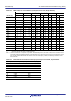
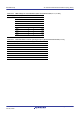


Table Of Contents
- 34. IrDA Interface
- 35. I2C-bus Interface (RIICa)
- 35.1 Overview
- 35.2 Register Descriptions
- 35.2.1 I2C-bus Control Register 1 (ICCR1)
- 35.2.2 I2C-bus Control Register 2 (ICCR2)
- 35.2.3 I2C-bus Mode Register 1 (ICMR1)
- 35.2.4 I2C-bus Mode Register 2 (ICMR2)
- 35.2.5 I2C-bus Mode Register 3 (ICMR3)
- 35.2.6 I2C-bus Function Enable Register (ICFER)
- 35.2.7 I2C-bus Status Enable Register (ICSER)
- 35.2.8 I2C-bus Interrupt Enable Register (ICIER)
- 35.2.9 I2C-bus Status Register 1 (ICSR1)
- 35.2.10 I2C-bus Status Register 2 (ICSR2)
- 35.2.11 Slave Address Register Ly (SARLy) (y = 0 to 2)
- 35.2.12 Slave Address Register Uy (SARUy) (y = 0 to 2)
- 35.2.13 I2C-bus Bit Rate Low-Level Register (ICBRL)
- 35.2.14 I2C-bus Bit Rate High-Level Register (ICBRH)
- 35.2.15 I2C-bus Transmit Data Register (ICDRT)
- 35.2.16 I2C-bus Receive Data Register (ICDRR)
- 35.2.17 I2C-bus Shift Register (ICDRS)
- 35.3 Operation
- 35.4 SCL Synchronization Circuit
- 35.5 SDA Output Delay Function
- 35.6 Digital Noise Filters
- 35.7 Address Match Detection
- 35.8 Automatic Low-Hold Function for SCL
- 35.9 Arbitration-Lost Detection Functions
- 35.10 Start Condition/Restart Condition/Stop Condition Generating Function
- 35.11 Bus Hanging
- 35.12 SMBus Operation
- 35.13 Interrupt Sources
- 35.14 Initialization of Registers and Functions When a Reset is Applied or a Condition is Detected
- 35.15 Event Link Function (Output)
- 35.16 Usage Notes
- 36. CAN Module (RSCAN)

R01UH0823EJ0110 Rev.1.10 Page 1003 of 1852
Nov 30, 2020
RX23W Group 33. Serial Communications Interface (SCIg, SCIh)
Table 33.22 BRR Settings for Various Bit Rates (Simple I
2
C Mode)
Bit Rate
(bps)
Operating Frequency PCLK (MHz)
8 10162025
n N Error (%) n N Error (%) n N Error (%) n N Error (%) n N Error (%)
10 k 0 24 0.0 0 31 –2.3 1 12 –3.8 1 15 –2.3 1 19 –2.3
25 k 0 9 0.0 0 12 –3.8 1 4 0.0 1 6 –10.7 1 7 –2.3
50 k 0 4 0.0 0 6 –10.7 1 2 –16.7 1 3 –21.9 1 3 –2.3
100 k 0 2 –16.7 0 3 –21.9 0 4 0.0 0 6 –10.7 1 1 –2.3
250 k 0 0 0.0 0 1 –37.5 0 1 0.0 0 2 –16.7 0 3 –21.9
350 k 0 1 –10.7 0 2 –25.6
Bit Rate
(bps)
Operating Frequency
PCLK (MHz)
30
n N Error (%)
10 k 1 23 –2.3
25 k 1 9 –6.3
50 k 1 4 –6.3
100 k 1 2 –21.9
250 k 0 3 –6.3
350 k 0 2 –10.7
Table 33.23 Minimum Widths at High and Low Level for SCL at Various Bit Rates (Simple I
2
C Mode)
Bit Rate
(bps)
Operating Frequency PCLK (MHz)
8101620
nN
Min. Widths at
High/Low Level
for SCL (µs) n N
Min. Widths at
High/Low Level
for SCL (µs) n N
Min. Widths at
High/Low Level
for SCL (µs) n N
Min. Widths at
High/Low Level
for SCL (µs)
10 k 0 24 43.75/50.00 0 31 44.80/51.20 1 12 45.50/52.00 1 15 44.80/51.20
25 k 0 9 17.50/20.00 0 12 18.20/20.80 1 4 17.50/20.00 1 6 19.60/22.40
50 k 0 4 8.75/10.00 0 6 9.80/11.20 1 2 10.50/12.00 1 3 11.20/12.80
100 k 0 2 5.25/6.00 0 3 5.60/6.40 0 4 4.37/5.00 0 6 4.90/5.60
250 k 0 0 1.75/2.00 0 1 2.80/3.20 0 1 1.75/2.00 0 2 2.10/2.40
350 k 0 1 1.40/1.60
Bit Rate
(bps)
Operating Frequency PCLK (MHz)
25 30
nN
Min. Widths at
High/Low Level
for SCL (µs) n N
Min. Widths at
High/Low Level
for SCL (µs)
10 k 1 19 44.80/51.20 1 23 44.80/51.20
25 k 1 7 17.92/20.48 1 9 18.66/21.33
50 k 1 3 8.96/10.24 1 4 9.33/10.66
100 k 1 1 4.48/5.12 1 2 5.60/6.40
250 k 0 3 2.24/2.56 0 3 1.86/2.13
350 k 0 2 1.68/1.92 0 2 1.40/1.60