
User's Manual


Target Board for RX23W 1. Overview
R01UHxxxEG0100
Rev.0.60 Page 9 of 28
Nov. 26, 2019
Block Diagram
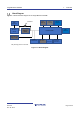
Figure 1-1 shows the block diagram of the Target Board for RX23W.
Figure 1-1: Block Diagram
Pmod™
Connector
MCU
Header x2
Arduino™
Connector
Reset Switch
User Switch
User LED x2
Emulator
Circuit
Main Clock
Sub Clock
External Power
Supply Header
Power
Indicator LED
*Gray hatching parts is not mounted.
Evaluation MCU
USB
Connector
Cut Pattern
Power Supply
Selection
Header
BLE
Antenna
USB
Connector