REJ10B0223-0140 32185/32186/32192/32195/32196 Group Starter Kit User’s Manual M3A-2154G52B All information contained in these materials, including products and product specifications, represents information on the product at the time of publication and is subject to change by Renesas Technology Corp. without notice. Please review the latest information published by Renesas Technology Corp. through various means, including the Renesas Technology Corp. website (http://www.renesas.com). Rev.1.
Notes regarding these materials 1. This document is provided for reference purposes only so that Renesas customers may select the appropriate Renesas products for their use. Renesas neither makes warranties or representations with respect to the accuracy or completeness of the information contained in this document nor grants any license to any intellectual property rights or any other rights of Renesas or any third party with respect to the information in this document. 2.
Precautions on Using The Product Described Herein 1. The product described herein should be used in combination with the parts included with the starter kit. If the product is operated in combination with any other item, its operation cannot be guaranteed. Nor will requests for help or suggestion be answered. 2. The product described herein was prepared for program development or evaluation purposes. The product cannot be used for the mass production. 3.
Preface Thank you very much for purchasing the 32185/32186/32192/32195/32196 Group Starter Kits, the M3A-2154G52B. This manual describes how to set up the hardware and software products included with the 32185/32186/32192/32195/32196 Group Starter Kit and the precautions to be observed when using those products. For details about the 32192/321296 or 32186 Group hardware and software products and development support tools, refer to the user’s manuals and related documentation supplied with them.
Contents 1. Overview........................................................................................................................1 1.1 1.2 Outline of the Starter Kit ...................................................................................................................... 1 System Configuration.......................................................................................................................... 2 2. Contents of the Product Package ................................
Appendix 2 Part List........................................................................................................31 Appendix 3 M3A-2154G02A Product Standards .............................................................33 1. Overview......................................................................................................................34 1.1 Outline of the Product ....................................................................................................................
32185/32186/32192/32195/32196 Group Starter Kit User’s Manual M3A-2154G52B 32185/32186/32192/32195/32196 Group Starter Kit User’s Manual M3A-2154G52B 1. Overview 1.1 Outline of the Starter Kit The M3A-2154G52B Starter Kit consists of M3A-2154G02A (32185/32186/32192/32195/32196 Group Evaluation Board; hereafter called the M3A-2154 Evaluation Board), M3T-PD32RM (Emulator Debugger for M32100T-EZ-E) and M3T-CC32R (Cross Tool Kit for the M32R Family; trial version).
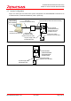
32185/32186/32192/32195/32196 Group Starter Kit User’s Manual M3A-2154G52B 1.2 System Configuration Figure 1.1 and Figure 1.2 below show system configurations of M3A-2154G52B connected to an included emulator, and M3A-2154G02A by itself, respectively.
32185/32186/32192/32195/32196 Group Starter Kit User’s Manual M3A-2154G52B 2. Contents of the Product Package This chapter shows the contents of the Starter Kit product package. When unpacking, check to see that all items are included with your package. 2.1 Packaged Product Items Table 2.1 shows the contents of the Starter Kit product package. Table 2.
32185/32186/32192/32195/32196 Group Starter Kit User’s Manual M3A-2154G52B 2.2 Contents of CD-ROM The CD-ROM contains the software, manuals, various data sheets, and sample programs which are needed for you to use the Starter Kit.
32185/32186/32192/32195/32196 Group Starter Kit User’s Manual M3A-2154G52B 3. Usage Precautions 3.1 Guaranteed Scope of the Starter Kit The Starter Kit was developed for users to trial the 32185/32186/32192/32195/32196 Group microcomputer specifications and development environment. Therefore, the results arising from the use of the Starter Kit are not guaranteed.
32185/32186/32192/32195/32196 Group Starter Kit User’s Manual M3A-2154G52B 3.4 About M3T-PD32RM The following describes precautions to be observed when using M3T-PD32RM. 3.4.1 Operating Manuals To use M3T-PD32RM of M3A-2154G52B, see the manuals shown below. 3.4.2 M3T-PD32RM release notes PD32RM Help About Break Operation M3T-PD32RM uses the M32R core’s internal debug circuit (SDI) to realize break functions.
32185/32186/32192/32195/32196 Group Starter Kit User’s Manual M3A-2154G52B (5) About hardware break Debug functions of M3T-PD32RM are realized by using the M32R core’s internal debug circuit (SDI), and not by using the emulator’s hardware resources based on bus signals and debug information from the MCU as in conventional emulators. The pre-execution PC break, post-execution PC break, and chip break alluses this internal debug circuit (SDI).
32185/32186/32192/32195/32196 Group Starter Kit User’s Manual M3A-2154G52B 3.5 About Evaluation Board When the evaluation board does not start operation after supplied power, check the following points. 3.5.1 Contact failure of IC Socket Oscillation or thermal expansion may cause a poor connection between microcomputers and IC socket on the Evaluation Board. Follow the steps below. - Screw down the top cover of IC socket with setscrews at four corners. The tightening torque shall be 0.054N.m.
32185/32186/32192/32195/32196 Group Starter Kit User’s Manual M3A-2154G52B 4. Starter Kit Usage Conditions The following shows the conditions under which the Starter Kit can be used. 4.1 Ambient Conditions Table 4.1 shows the ambient conditions under which the Starter Kit can be used. Table 4.1 Operating Environment Symbol Parameter Topr Operating ambient temperature Tstr Storage ambient temperature 4.2 Rated value 5oC to 35oC 0oC to 60oC Remarks No dewdrops allowed.
32185/32186/32192/32195/32196 Group Starter Kit User’s Manual M3A-2154G52B 5. Hardware Setup This chapter describes how to set up the hardware components necessary to use the Starter Kit. Table 5.1 and Table 5.2 show how to set up the hardware components. Table 5.1 Hardware Setup Procedure Set the emulator 1st (Refer to 5.1.1) When using the evaluation board by itself — Connect the host PC and emulator 2nd (Refer to 5.1.
32185/32186/32192/32195/32196 Group Starter Kit User’s Manual M3A-2154G52B 5.1.2 M3A-2154 Evaluation Board Power Supply and Setting The following shows how to set the M3A-2154 Evaluation Board. Use a 5V DC power supply to feed power to the M3A-2154 Evaluation Board. Use included 5V power supply cable to connect the 5V DC power supply and CN2 connector included with the M3A-2154 Evaluation Board. The Connecting when Feeding Power to the M3A-2154 Evaluation Board is shown in Figure 5.2.
32185/32186/32192/32195/32196 Group Starter Kit User’s Manual M3A-2154G52B 5.2 5.2.1 Hardware Setup when the Evaluation Board by Itself in Use M3A-2154 Evaluation Board Power Supply and Settings The following shows how to set the M3A-2154 Evaluation Board. Use a 5V DC power supply to feed power to the M3A-2154 Evaluation Board. Use an included 5V power supply cable to connect the 5V DC power supply and CN2 connector included with the M3A-2154 Evaluation Board.
32185/32186/32192/32195/32196 Group Starter Kit User’s Manual M3A-2154G52B 6. Software Setup 6.1 M3T-PD32RM M3T-PD32RM is the debugger software that controls M32100T-EZ-E from the host PC. 6.1.1 Installing M3T-PD32RM [Notes] Make sure that the installer is executed by one who is authorized as an Administrator when Windows 2000/XP is used as an operating system of the host machine. No one but the user who has the authority of an Administrator can install M3T-PD32RM. (1) Run pd32rmv301r00_e.
32185/32186/32192/32195/32196 Group Starter Kit User’s Manual M3A-2154G52B 6.1.2 Starting M3T-PD32RM Before starting M3T-PD32RM, make sure the hardware components have been set up in accordance with the instructions in 5.1 M3A-2154 Evaluation Board Hardware Setup, and that the Starter Kit hardware system (M3A-2154 Evaluation Board and M32100T-EZ-E) have been powered on. Make sure that M3T-PD32RM cannot be started unless the power to the hardware system is turned on.
32185/32186/32192/32195/32196 Group Starter Kit User’s Manual M3A-2154G52B Setting CPU Clock Case of using 32192 or 32195 or 32196 Group, while the MCU tab is open, select the “160” for the appropriate CPU Clock. Case of using 32185 or 32186 Group, while the MCU tab is open, select the “80” for the appropriate CPU Clock. Checking Serial No. While the MCU tab is open, make sure the Serial No. is in accordance with the following. M3T-PD32RM can be started only with Serial No. as follows: Table 6.2 Serial No.
32185/32186/32192/32195/32196 Group Starter Kit User’s Manual M3A-2154G52B When you have finished the above initialization, click the “OK” button to start M3T-PD32RM. If M3T-PD32RM communicates normally with the target system, it starts up and the M3T-PD32RM window shown in Figure 6.4 appears. For details on how to use it, refer to the PD32RM Help. Figure 6.4 M3T-PD32RM Window at Normal Startup 6.1.
32185/32186/32192/32195/32196 Group Starter Kit User’s Manual M3A-2154G52B 6.1.4 Terminating M3T-PD32RM To terminate M3T-PD32RM, choose [File] -> [Exit] from the pulldown menu. Then, a dialog box appears prompting you for your confirmation (see Figure 6.6). Click the “OK” button in that dialog box to quit M3T-PD32RM. Or click the “Cancel” button, in which case M3T-PD32RM does not terminate. Cancel Figure 6.6 Dialog Box for Confirming Whether to Quit M3T-PD32RM REJ10B0223-0140/Rev.1.40 Jan.
32185/32186/32192/32195/32196 Group Starter Kit User’s Manual M3A-2154G52B 6.2 M3T-CC32R 6.2.1 (1) (2) (3) (4) Installing M3T-CC32R Run cc32rv500r00_e.exe that is included in the Eng \ Tool \ Cc32r directory of the CD-ROM. Proceed to install M3T-CC32R following messages on the installation screen. When you are asked to select the license type of M3T-CC32R, select “Trial License”. While installing M3T-CC32R, you will be asked to confirm whether to change AUTOEXEC.BAT variables.
32185/32186/32192/32195/32196 Group Starter Kit User’s Manual M3A-2154G52B Appendix 1 Contents of CD-ROM 1. Contents of CD-ROM The CD-ROM contains the software, manuals, various data sheets, and sample programs which are needed for you to use the Starter Kit.
32185/32186/32192/32195/32196 Group Starter Kit User’s Manual M3A-2154G52B 1.1 Acrobat The CD-ROM contains files necessary to read manuals (PDF files). The documents included in the CD-ROM have been verified to be displayed and printed using the following versions of Acrobat. If you have trouble displaying or printing documents with other Acrobat versions, install the appropriate Acrobat version from the CD-ROM into your computer. (English version) Eng + AcrobatReader + V3 + (For Windows95) | + Ar32e301.
32185/32186/32192/32195/32196 Group Starter Kit User’s Manual M3A-2154G52B 1.2 (1) Tool M3T-CC32R M3T-CC32R (Cross Tool Kit for the M32R Family, trial version whose useful period is limited) is included. Its directory structure is shown below. (English version) Eng+Tool+Cc32r+ + cc32rv500r00_e.exe + rej10j0931_as32r_u.pdf + rej10j0930_cc32r_u.pdf + mapue.
32185/32186/32192/32195/32196 Group Starter Kit User’s Manual M3A-2154G52B (3) M3S-KD32R (Discontinued) M3S-KD32R (Debugger for the Starter Kit) is included. This debugger software (Windows -compliant version) is used to control the microcomputer on the evaluation board from the host PC by connecting it and the host PC with LPT parallel cable through the M3A-2195 (SDI Interface Board). Its directory structure is shown below. (English version) Eng+Tool+Kd32r+ + KD32RNE.
32185/32186/32192/32195/32196 Group Starter Kit User’s Manual M3A-2154G52B (5) Oldversion Old versions of tools are included. Its directory structure is shown below. (English version) Eng+Tool+Oldversion+ + Cc32rv3 + Cc32rv41 + Cc32rv42 + Cc32rv43 + Pd32rmv2 + Pd32rmv21 + Pd32rmv3 + Kd32rv3 (Japanese version) Jpn+Tool+Oldversion+ + Cc32rv3 + Cc32rv41 + Cc32rv42 + Cc32rv43 + Pd32rmv2 + Pd32rmv21 + Pd32rmv3 + Kd32rv3 + Ufla32rv13 REJ10B0223-0140/Rev.1.
32185/32186/32192/32195/32196 Group Starter Kit User’s Manual M3A-2154G52B 1.3 Manual The M32R Family related manuals and data sheets are included in PDF file format. (English version) Eng + Manual + + Readme_e.txt + e32rsm.pdf + rej09b0112_32fpusm.pdf : README file : M32R Family software manual : M32R-FPU software manual + e32170um.pdf + e32172um.pdf + rej06b0048_32180um.pdf + rej09b0014_32182um.pdf + rej09b0015_32171um.pdf + rej09b0067-0110_32176hm.pdf + rej09b0123-0101_32192hm.
32185/32186/32192/32195/32196 Group Starter Kit User’s Manual M3A-2154G52B 1.4 Board Related Manual (Document) The product standards, part list, connection diagrams and user’s manuals for the evaluation board in Starter Kit are included in PDF file format. (1) M3A-2114 Evaluation Board related documents The related documents for the 32170/32171/32172/32173/32174 Group Evaluation Board are included in PDF file format. (English version) Eng+Document+M3A-2114+ + Readme_e.txt : README file + 2114um_e.
185/32186/32192/32195/32196 Group Starter Kit User’s Manual M3A-2154G52B (3) M3A-2152 Evaluation Board related documents The related documents for the 32176 Group Evaluation Board are included in PDF file format. (English version) Eng+Document+M3A-2152+ + Readme_e.txt + rej10b0224_2152um.pdf : README file : M3A-2152 Starter Kit use’s manual (Japanese version) Jpn+Document+M3A-2152+ + Readme_j.txt : README file + rjj10b0233_2152um.
32185/32186/32192/32195/32196 Group Starter Kit User’s Manual M3A-2154G52B (6) (7) M3A-2191 Pitch Converter related documents The M3A-2114 Evaluation Board and M3A-2195 Interface Board connecting pitch converter related documents are included in PDF file format. (English version) Eng+Document+M3A-2191+ + Readme_e.txt + rej10b0228_2191sk.pdf + cdrom_e.pdf : README file : M3A-2191 product standards : Content list of CD-ROM (Japanese version) Jpn+Document+M3A-2191+ + Readme_j.txt + rjj10b0237_2191sk.
32185/32186/32192/32195/32196 Group Starter Kit User’s Manual M3A-2154G52B (8) M3A-2195 SDI Interface Board related documents (Discontinued) The SDI Interface Board documents are included in PDF file format. (English version) Eng+Document+Discontinued_model+M3A-2195+ + Readme_e.txt : README file + 2195g50sk_e.pdf : M3A-2195G50 product standards + 2195c_e.pdf : M3A-2195 Evaluation Board connection diagram + 2195p_e.pdf : M3A-2195 part list + 2195g50p_e.pdf : M3A-2195G50 part list + 2195um_e.
32185/32186/32192/32195/32196 Group Starter Kit User’s Manual M3A-2154G52B (11) M3A-2142G04 Board related documents (Discontinued) The related documents for the MCU pin processing Board are included in PDF file format. (English version) Eng+Document+Discontinued_model+M3A-2142G04+ + Readme_e.txt : README file + 2142g04sk_e.pdf : M3A-2142G04 product standards + cdrom_e.pdf : Content list of CD-ROM (Japanese version) Jpn+Document+Discontinued_model+M3A-2142G04+ + Readme_j.txt : README file + 2142g04sk_j.
32185/32186/32192/32195/32196 Group Starter Kit User’s Manual M3A-2154G52B 1.
32185/32186/32192/32195/32196 Group Starter Kit User’s Manual M3A-2154G52B Appendix 2 Part List A part list is provided in following pages for your reference. REJ10B0223-0140/Rev.1.40 Jan.
REJ10B0223-0140/Rev.1.40 Jan. 2007 Page 32 of 79 PLL-M3A-2154G02A Part No. M3A-2154G02A Part Type Name (Drawing No.,Product Specification) PPL-M3A-2154G52B Revision No. Special note: (1) Blank columns denote the same content as the upper row. (2) If two or more part type names are written for one part, the upper row has priority. (3) The asterisk (*) in the item No. column denotes that the rest is blank.
32185/32186/32192/32195/32196 Group Starter Kit User’s Manual M3A-2154G52B Appendix 3 M3A-2154G02A Product Standards This manual describes how to operate the M3A-2154G02A (32185/32186/32192/32195/32196 Group Evaluation Board) REJ10B0223-0140/Rev.1.40 Jan.
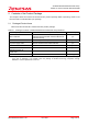
32185/32186/32192/32195/32196 Group Starter Kit User’s Manual M3A-2154G52B 1. Overview 1.1 Outline of the Product Table 1.1 Mounted Microcomputer Type Mounted microcomputer type name M32192F8VFP Default M32186F8VFP (Note1) Evaluation board type name (socket mounted type) M3A-2154G02A Note1: Using M32186F8VFP, setting of oscillator circuit should be changed. For details, refer to chapter 2.5 Oscillator circuit. Table 1.
32185/32186/32192/32195/32196 Group Starter Kit User’s Manual M3A-2154G52B 1.2 External View An external view of the M3A-2154G02A is shown below. Figure 1.2 External View of the M3A-2154G02A REJ10B0223-0140/Rev.1.40 Jan.
32185/32186/32192/32195/32196 Group Starter Kit User’s Manual M3A-2154G52B 1.3 Block Diagram A block diagram of the M3A-2154G02A is shown below.
32185/32186/32192/32195/32196 Group Starter Kit User’s Manual M3A-2154G52B 1.4 Specifications of the Evaluation Board 1.4.1 Electrical Characteristics Table 1.3 Electrical Characteristics Symbol Parameter Rated Value VCCE,VCC-BUS Power supply voltage 4.75 V to 5.25 V Tstr Storage ambient temperature 0°C to 60°C Topr Operating ambient temperature 5°C to 35°C Note: Operating conditions require that no dewdrops and corrosive gas be present. 1.4.2 Functional Characteristics Table 1.
32185/32186/32192/32195/32196 Group Starter Kit User’s Manual M3A-2154G52B 2. Functional Specifications 2.1 Configuration of the Power Supply The power to the M32R/ECU can be supplied from two sources, VCC-BUS and VCCE, independently of each other. With default settings, the power to the M32R/ECU is fed through the VCCE power supply connector to all of its internal circuits.
32185/32186/32192/32195/32196 Group Starter Kit User’s Manual M3A-2154G52B Table 2.
32185/32186/32192/32195/32196 Group Starter Kit User’s Manual M3A-2154G52B 2.2 FP Select Circuit The FP select circuit is used for reprogramming the internal flash memory of the M32R/ECU. This circuit is configured in such a way that FP is switched from the EXTFP signal of extension connector (CON2) by using a jumper (J10). VCCE CON2 FX1-144S-1.
32185/32186/32192/32195/32196 Group Starter Kit User’s Manual M3A-2154G52B 2.3 MOD Select Circuit This circuit is used to set operation modes of the M32R/ECU. The MOD0 power supply is configured in such a way that MOD0 is switched from the EXTMOD0 signal of extension connector (CON2) by using a jumper (J8). The MOD1 power supply defaults to 0 V. The MOD2 power supply is fixed to 0 V. CON2 FX1-144S-1.
32185/32186/32192/32195/32196 Group Starter Kit User’s Manual M3A-2154G52B 2.4 Serial I/O Interface The evaluation board is interfaced to the host PC (Windows) through its RS-232C by using SIO of the M32R/ECU. Of the RS-232C control signals, only TXD and RXD are used for connection to the host PC (Windows). The unused CTS and RTS are directly-coupled to configure a loop-back. The unused DSR and DTR also are configured in a similar manner.
32185/32186/32192/32195/32196 Group Starter Kit User’s Manual M3A-2154G52B Table 2.5 Channel Selection by a Rotary Switch Rotary switch position SIO Selected channel 0 SIO0 1 SIO1 2 SIO2 3 SIO3 4 SIO0 5 SIO1 6 SIO2 7 SIO3 8 SIO0 9 SIO1 Table 2.
32185/32186/32192/32195/32196 Group Starter Kit User’s Manual M3A-2154G52B 2.5 Oscillator Circuit The oscillator circuit can be selected from three options by using the jumper J1: a surface mount-type 20 MHz crystal oscillator module, a surface mount-type 10 MHz crystal oscillator module or a crystal resonator. By default, the surface mount-type 20 MHz crystal oscillator module is selected.
32185/32186/32192/32195/32196 Group Starter Kit User’s Manual M3A-2154G52B 2.6 General-purpose Output Port LED Indicators The LED indicators (L0–L7) are used to indicate the status of the M32R/ECU ports P110–P117. VCCE U1 M32R/ECU U6 TC74HC540AF L0 P110 L1 P111 L2 P112 L3 P113 L4 P114 L5 P115 L6 P116 L7 P117 CON1 FX1-144S-1.27DS P110 P111 P112 P113 P114 P115 * CONx : Connector * Lx : LED * Ux : IC P116 P117 Figure 2.6 LED Indicator Block for the General-purpose Output Ports Table 2.
32185/32186/32192/32195/32196 Group Starter Kit User’s Manual M3A-2154G52B 2.7 General-purpose Input Port Control Circuit The general-purpose input port control circuit is used to control the status of the M32R/ECU ports P130–P137 by using toggle switches (S0–S7). For the settings of jumpers J16 and J17, see the Section 2.9 CAN Interface.
32185/32186/32192/32195/32196 Group Starter Kit User’s Manual M3A-2154G52B Table 2.10 Relationship Between Toggle Switches and Ports Corresponding Toggle Switch Name M32R/ECU Port S0 P130 Table 2.11 Toggle Switch Positions Lever Direction Port Input Level Up High S1 P131 Middle Open S2 P132 Down Low S3 P133 S4 P134 S5 P135 S6 P136 S7 P137 Down Lever direction Up Port input level Middle H Open L Figure 2.8 Toggle Switch Positions REJ10B0223-0140/Rev.1.40 Jan.
32185/32186/32192/32195/32196 Group Starter Kit User’s Manual M3A-2154G52B 2.8 Analog Port Input Control Circuit The analog port input control circuit is used to control the status of the M32R/ECU analog ports AD0IN0 and AD0IN1 by using VR controls VOL0 and VOL1. U1 M32R/ECU VCCE VCCE J12 2 1 J13 2 1 AD0IN0 AD0IN1 VOL0 VOL1 CON1 FX1-144-1.27DS AD0IN0 * CONx : Connector * Jx : Jumper * Ux : IC * VOLx : VR control AD0IN1 Figure 2.9 Analog Port Input Control Circuit Table 2.
32185/32186/32192/32195/32196 Group Starter Kit User’s Manual M3A-2154G52B 2.9 CAN Interface The evaluation board is interfaced to a CAN-mounted system by using the internal CAN functions of the M32R/ECU.
32185/32186/32192/32195/32196 Group Starter Kit User’s Manual M3A-2154G52B Table 2.
32185/32186/32192/32195/32196 Group Starter Kit User’s Manual M3A-2154G52B 2.10 JTAG/NBD Interface The JTAG connector for Renesas SDI, XCN1 consists of the 2.54-mm contact pitch XG4C-1034 made by Omron Corporation. The NBD connector, CN4 consists of the 2.54-mm contact pitch XG4C-1434 made by Omron Corporation.
32185/32186/32192/32195/32196 Group Starter Kit User’s Manual M3A-2154G52B Table 2.16 JTAG Interface Connector Pin Assignments Connector Pin No Signal Name Name 1 JTCK XCN1 Test clock 2 GND Ground 3 JTDI Test data input 4 JTDO Test data output 5 JTMS Test mode select 6 JTRST Test reset 7 JDBI Break request 8 VCCE Power supply 9 JVCC User system power supply monitor 10 RESET Table 2.17 NBD Interface Connector Pin Assignments Connector Pin No.
32185/32186/32192/32195/32196 Group Starter Kit User’s Manual M3A-2154G52B 3. Reference Data 3.1 Jumper and Test Pin Lists 3.1.1 Jumpers Table 3.1 Jumper List Jumper No.
32185/32186/32192/32195/32196 Group Starter Kit User’s Manual M3A-2154G52B 3.2 Extension Connectors CON1 and CON2 3.2.1 Pin Assignments of the Extension Connector CON1 1st pin Bard edge CON1 120 108 96 84 72 60 48 36 24 12 114 102 90 78 66 54 42 30 18 6 3rd pin Figure 3.1 CON1 Connector Pin Assignments (View from Side of Mounted Items) Table 3.3 CON1 Connector Pin Assignments Signal Signal Pin No. Pin No.
32185/32186/32192/32195/32196 Group Starter Kit User’s Manual M3A-2154G52B 3.2.2 Pin Assignments of the Extension Connector CON2 1st pin Board edge 3rd pin 234 222 210 198 186 174 162 150 138 126 CON2 240 228 216 204 192 180 168 156 144 132 Figure 3.2 CON2 Connector Pin Assignments (View from Side of Mounted Items) Table 3.4 CON2 Connector Pin Assignments Signal Signal Pin No. Pin No. Name Name 1 (121) P96 31 (151) NC 61 (181) Signal Name P174 91 (211) Signal Name P1 Pin No. Pin No.
32185/32186/32192/32195/32196 Group Starter Kit User’s Manual M3A-2154G52B 3.3 CAN Cable (1) External View CC1:Modular plug CC2:Dsub connector 100mm 1 5 9 1 6 6 Figure 3.3 External View (2) CC1 and CC2 Connections Table 3.5 Connection Table CN1 CN2 Pin No. Pin Name Pin Name Pin No. 1 — NC 1 2 CANL (blue) CANL 2 3 — GND 3 4 CANH (white) NC 4 5 GND (black) NC 5 6 — NC 6 CANH 7 NC 8 NC 9 REJ10B0223-0140/Rev.1.40 Jan.
32185/32186/32192/32195/32196 Group Starter Kit User’s Manual M3A-2154G52B 3.4 Connection Diagram A connection diagram is provided in following pages for your reference. REJ10B0223-0140/Rev.1.40 Jan.
1 2 3 4 CP4 0.1u AVCC0 CP5 0.
1 2 3 4 R5 SML-211UT LED1 1K A + CP15 47u VCCE + CP16 47u Power line Cap. S2B-XH-A 1 2 VCCE power supply CN2 S2B-XH-A(OPEN) 1 2 VCCBUS power supply CN1 1 3 2 D2 MA738(OPEN) JP-3PIN(OPEN) J3 2 2 J7 2 B + J6 D1 VIN U3 10u(OPEN) C4 3 JP-2PIN(OPEN) 1 1 2 VDDE VREF0 AVCC0 VCCER VCCE VCC-BUS VOUT 2 LT1086CM-3.3(OPEN) MA738(OPEN) 0.1u CP14 0.1u CP11 0.1u CP13 0.1u CP12 JP-2PIN(OPEN) JP-2PIN(OPEN) 1 J5 CP10 0.
1 2 3 1:NBDCLK 2:GND 3:NBDSYNC# 4:NBDEVNT# 5:RESET 6:GND 7:JVCC 8:NBDD3 9:NBDD2 10:GND 11:NBDD1 12:NBDD0 13: 14: 1:CANH1 2:CANL1 3:CANH2 4:CANL2 5:GND 6: 7:GND 8: A XG4C-1434 1 2 3 4 5 6 7 8 9 10 11 12 13 14 CN4 TM2REA-1208 1 2 3 4 5 6 7 8 CN3 VCCE 4 3 2 1 RA11 33 5 6 7 8 JTDI_NBD 2 JTDO_NBD 2 RESET_NBD 2 JTCK_NBD 2 NBD I/F TX7 B TX11 JP-2PIN J9 VCCE CP26 0.1uF(OPEN) R17 CP22 0.1u(OPEN) 100K RA4 B JP-2PIN J11 TEST PIN(OPEN) CP21 0.1u(OPEN) R14 CP17 0.
Jan. 2007 1 2 3 4 A 1,6 P117 1,6 P116 1,6 P115 1,6 P114 1,6 P113 1,6 P112 1,6 P111 1,6 P110 A RA7 VCCE 100K 1 2 3 4 6 7 8 9 5 10 VOL0 RK09K1110B26 VOL1 RK09K1110B26 1 1 VCC GND 2 2 B JP-2PIN(OPEN) J13 Y1 Y2 Y3 Y4 Y5 Y6 Y7 Y8 20 10 18 17 16 15 14 13 12 11 TC74HC540AF G1 G2 A1 A2 A3 A4 A5 A6 A7 A8 JP-2PIN(OPEN) J12 1 19 2 3 4 5 6 7 8 9 U6 B AD0IN1 1,6 AD0IN0 1,6 0.
Jan. 2007 1 2 3 4 1 2 3 4 5 6 7 8 9 : : : : : : : : : E DCD RXD TXD DTR SG DSR RTS CTS RI 1 1A 2A 4A 8A XM2C-0912 1 6 2 7 3 8 4 9 5 DR-KR10H C SW2 CN5 VCCE 2 3 4 5 5 6 7 8 4 3 2 1 5 E 0.1u C8 2 6 13 8 14 7 VCCE 0.1u C6 100K RA10 D 16 8 6 4 5 1 2 3 Y0 Y1 Y2 Y3 Y4 Y5 Y6 Y7 15 14 13 12 11 10 9 7 TC74VHC138FT VCC GND G1 G2A G2B A B C U7 R1OUT R2OUT T1IN T2IN C2- C1C2+ C1+ GND VCC C7 12 9 11 10 5 0.1u 3 0.1u 4 C9 1 15 16 0.
REJ10B0223-0140/Rev.1.40 Jan.
32185/32186/32192/32195/32196 Group Starter Kit User’s Manual M3A-2154G52B 3.5 Part List A part list is provided in following pages for your reference. REJ10B0223-0140/Rev.1.40 Jan.
REJ10B0223-0140/Rev.1.40 Jan. 2007 Page 65 of 79 M32R/ECU#6HL Microcomputer socket Microcomputer socket Reset IC Regulator CAN driver IC LED driver IC Decoder IC Bus switch IC RS232C driver IC Oscillator Oscillator Resonator Switch (push type) Operating unit for SW1 Rotary switch 2 3 4 5 6 7 8 9 10 11 12 13 14 15 16 17 SW2 For SW1 SW1 Y1 X2 X1 U9 U8 U7 U6 U4, 5 U3 U2 U1 U1 U1 U1 Part No.
REJ10B0223-0140/Rev.1.40 Jan. 2007 Page 66 of 79 Test pin 33 Part No. CP27-31,C6-9 CP4,5,8-14,20,25, CP1-3 TX2-5 TX1,6-18 LED1, L0-7 J4,5,6,7,12,13 J9,11 J14-20 J2,3,8,10 J1 XCN1 CON1,2 CN5 CN4 CN3 CN2 CN1 S0-7 Part Name GRM219F11H104ZA01(0.1uF) Special note: Murata Murata Mac-Eight Mac-Eight Rohm Honda Tsushin Kogyo Honda Tsushin Kogyo Honda Tsushin Kogyo Honda Tsushin Kogyo Honda Tsushin Kogyo Omron Hirose Omron Omron Hirose J.S.T. Mfg. J.S.T. Mfg.
REJ10B0223-0140/Rev.1.40 Jan.
REJ10B0223-0140/Rev.1.40 Jan.
32185/32186/32192/32195/32196 Group Starter Kit User’s Manual M3A-2154G52B 3.6 Pattern Diagram A pattern diagram for the board is provided in following pages for your reference. REJ10B0223-0140/Rev.1.40 Jan.
REJ10B0223-0140/Rev.1.40 Jan. 2007 Page 70 of 79 DRAWING No.
REJ10B0223-0140/Rev.1.40 Jan. 2007 Page 71 of 79 DRAWING No.
REJ10B0223-0140/Rev.1.40 Jan. 2007 Page 72 of 79 DRAWING No.
REJ10B0223-0140/Rev.1.40 Jan. 2007 Page 73 of 79 DRAWING No.
REJ10B0223-0140/Rev.1.40 Jan. 2007 Page 74 of 79 DRAWING No.
REJ10B0223-0140/Rev.1.40 Jan. 2007 Page 75 of 79 DRAWING No.
32185/32186/32192/32195/32196 Group Starter Kit User’s Manual M3A-2154G52B 3.7 Diagram of External Dimension A diagram of external dimension for the board is provided in following pages for your reference. REJ10B0223-0140/Rev.1.40 Jan.
REJ10B0223-0140/Rev.1.40 Jan. 2007 Page 77 of 79 CHANGE DRAWI NG No. PG D A TE I TEM DRAW N CHECKED 3RD ANGLE PROJECTION DESIG N DIM IN mm DESCRIPTIO N DATE 05-10-4 / APPROVED NTS Hole Diameter shows the finished diameter of each hole. is 3.2 mounting hole. [Example] shows the hole symbol of the mounting hole.
32185/32186/32192/32195/32196 Group Starter Kit User’s Manual M3A-2154G52B 3.8 Setting Jumper by Cutting Pattern Some jumpers are shorted at default condition by pattern wiring on the reverse side of printed circuit board. Case of setting the condition except for default, the following setting is required. Note: Case that the printed circuit board is cut pattern by user, the product is except from repairable list. 3.8.
32185/32186/32192/32195/32196 Group Starter Kit User’s Manual M3A-2154G52B 3.9 Description of Board Silk The color of board silk indicates solder specification when the items on board are mounted. Table 3.7 Difference in the Color of Board Silk Color of board silk Solder specification when the items on board are mounted White Using nonlead-free soldering Yellow Using lead-free soldering REJ10B0223-0140/Rev.1.40 Jan.
REVISION HISTORY Rev. Date 32185/32186/32192/32195/32196 Group Starter Kit User’s Manual M3A-2154G52B Description Page Summary 1.00 Oct. 10, 2004 — First edition 1.30 Oct. 16, 2006 — - Added the board M3A-2154G02A product (Appendix 3) - Added the 32185 Group and the 32195 Group to the starter kit applicable microcomputer - Updated a setup method along with the tool update (Chapter 6) - Updated contents of CD-ROM (Appendix 1) - Updated a diagram of the external dimension. (Appendix 3.3.7) 1.
Sales Strategic Planning Div. Nippon Bldg., 2-6-2, Ohte-machi, Chiyoda-ku, Tokyo 100-0004, Japan RENESAS SALES OFFICES http://www.renesas.com Refer to "http://www.renesas.com/en/network" for the latest and detailed information. Renesas Technology America, Inc. 450 Holger Way, San Jose, CA 95134-1368, U.S.A Tel: <1> (408) 382-7500, Fax: <1> (408) 382-7501 Renesas Technology Europe Limited Dukes Meadow, Millboard Road, Bourne End, Buckinghamshire, SL8 5FH, U.K.
32185/32186/32192/32195/32196 Group Starter Kit User’s Manual M3A-2154G52B