
Starter Kit User's Manual

32185/32186/32192/32195/32196 Group
Starter Kit User’s Manual M3A-2154G52B
REJ10B0223-0140/Rev.1.40 Jan. 2007 Page 44 of 79
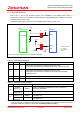
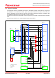
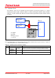
2.5 Oscillator Circuit
The oscillator circuit can be selected from three options by using the jumper J1: a surface
mount-type 20 MHz crystal oscillator module, a surface mount-type 10 MHz crystal oscillator
module or a crystal resonator. By default, the surface mount-type 20 MHz crystal oscillator module
is selected.
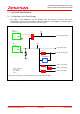
Figure 2.5 Oscillator Circuit
Note: The shaded sections in the above diagram have only patterns available. When using the resonator Y1, please be
sure to add capacitors (C1, C2) and a resistor (R2, R4).
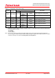
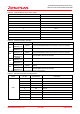
Table 2.8 Oscillator Circuit Connections (Jumper)
Name Condition Description
Shorted
between 1–4
Default Outputs a clock from X1 (surface mount-type oscillator module)
Shorted
between 2–4
(Note1) Outputs a clock from X2 (surface mount-type oscillator module)
J1
Shorted
between 3–4
Outputs a clock from Y1 (resonator)
Note1: Using M32186F8VFP, the J1 jumper should be shorted between 2-4.
U1
M32R/ECU
XOUT
J1
1
2
X1
XIN
Surface mount-type
oscillator module
10MHz
OUT
Surface mount-type
oscillator module
20MHz
C1
R2
R4
Y1
X2
C2
OUT
3
4
* Cx : Capacitor
* Jx : Jumper
* Rx : Resister
* Ux : IC
* Xx : Oscillator modules
* Yx : Resonator