
Converter Board User's Manual


(3/4)
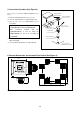
5. Connection Procedure (See Figure 3)
The procedure for connecting the R0E5212BACFK00 is shown
below.
(1) Mount the NQPACK064SD-ND on the user system.
(2) Attach the YQPACK064SD to the NQPACK064SD-ND.
(3) Secure the four corners of the YQPACK064SD with the
YQ-GUIDE's.
● Do not use the screws included with the
YQPACK064SD for fixing the YQPACK064SD.
● The screwdriver included with the
NQPACK064SD-ND is used for fixing the
HQPACK064SD. Do not use it for fixing the
YQ-GUIDE's.
(4) Attach the R0E521000EPB00 or R0E521000CPE00 to the
R0E5212BACFK00.
(5) Attach the R0E5212BACFK00 to the YQPACK064SD.
64-pin 0.5mm pitch
(PLQP0064KB-A) foot pattern
YQ-GUIDE(×4)
YQPACK064SD
NQPACK064SD-ND
(1)
(2)
(4)
(5)
R0E5212BACFK00
(3)
V
Be sure to use a
flathead screwdriver
R0E521000EPB00
or
R0E521000CPE00
Figure 3 Connection procedure of the R0E5212BACFK00
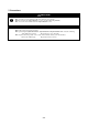
6. External Dimensions and a Sample Foot Pattern (See Figure 4)
Figure 4 External dimensions and a sample foot pattern of the R0E5212BACFK00
35.0
16.5 32.0
0.25
0.5
10.0
14.0
10.0
14.0
Unit: mm
R0E5212BACFK00 REV.A
MADE IN JAPAN