
Datasheet


Rev. 2.00 Sep. 28, 2009 Page xiii of xl
REJ09B0452-0200
Item Page Revision (See Manual for Details)
17.3.8 FIFO Control
Register (FFCR)
502 Table amended
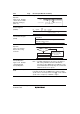
Bit Bit Name Initial Value R/W Description
2 XMITFRST 0 W Transmit FIFO Reset
The transmit FIFO data is cleared when 1 is written.
However, FTSR data is not cleared. This bit is
automatically cleared.
1 RCVRFRST 0 W Receive FIFO Reset
The receive FIFO data is cleared when 1 is written.
However, FRSR data is not cleared.
This bit is automatically cleared
.
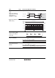
17.4.4 Data
Transmission/Reception
with Flow Control
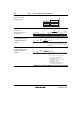
Figure 17.6 Example of
Initialization Flowchart
519 Figure amended
[5] Select parity with the EPS and PEN bits in FLCR, and
set the stop bit with the STOP bit in FLCR. Then, set
the data length with the CLS1 and CLS0 bits in FLCR.
[6] Set the FIFOE bit in FFCR to 1 to enable the FIFO.
Set the receive FIFO trigger level with the RCVRTRIG1
and RCVRTRIG0 bits in FFCR. Select the best trigger
level to prevent an overflow of the receive FIFO.
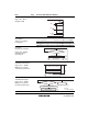
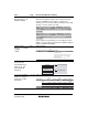
Figure 17.10 Example
of Data Reception
Flowchart
523 Figure amended
Read FLSR
Receive data ready interrupt
Read receive FIFO
Read FLSR
Error processing
BI = 1, FE = 1,
PE = 1, or OE = 1
No
Yes
[2]
[3]
[1]
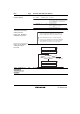
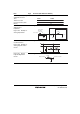
17.6.2 FLCR Access
During Serial
Transmission and
Reception
528 Description added