
Datasheet


Rev. 2.00 Sep. 28, 2009 Page xiv of xl
REJ09B0452-0200
Item Page Revision (See Manual for Details)
18.4.5 Slave Receive
Operation
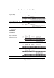
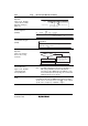
Figure 18.15 Example
of Slave Receive Mode
Operation Timing (2)
(MLS = 0)
573 Figure amended
ICDRR
[8] IRIC clear
[9] Set ACKB=1
[10] ICDR read (Data (n-1))
User processing
Data (n-2)
Data (n-1)
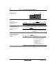
19.3.2 Keyboard Buffer
Control Register 2
(KBCR2)
593 Table amended
Bit Bit Name
Initial
Value R/W Description
7 to 4 — All 1 R/W Reserved
These bits are always read as 1. The initial value
should not be chan
ged.
19.3.6 Keyboard Buffer
Transmit Data Register
(KBTR)
598 Table amended
Description
Keyboard Buffer Transmit Data Register 7 to 0
Initialized to H'FF at re
set.
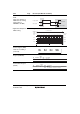
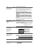
19.4.1 Receive
Operation
Figure 19.3 Sample
Receive Processing
Flowchart
565 Figure amended
KCLKI
and KDI bits both
1?
Set KBE bit
Receive enabled state
Keyboard side in data
transmission state.
Execute receive abort
processing.
[3]
Yes
No
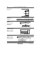
19.4.9 KCLK Fall
Interrupt Operation
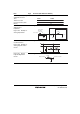
Figure 19.14 Example
of KCLK Input Fall
Interrupt Operation
608 Note amended
Note: * The KBF setting timing is the same as the timing of
KBF setting and KCLK automatic I/O inhibit bit
generation in figure 19.11. When the KBF bit is used
as the KCLK input fall interrupt flag, the automatic I/O
inhibit function does not operate.
19.5.4 Medium-Speed
Mode
614 Description amended
In medium-speed mode, the PS2 operates with the medium-
speed clock. For normal operation of the PS2, set the medium-
speed clock to a frequency of 300 kHz or higher.